Capacitive level sensor

a liquid level sensor and capacitive technology, applied in liquid/fluent solid measurement, instruments, machines/engines, etc., can solve problems such as limited dynamic rang

Inactive Publication Date: 2015-05-07
KONINKLJIJKE PHILIPS NV
View PDF63 Cites 21 Cited by
  • Summary
  • Abstract
  • Description
  • Claims
  • Application Information

AI Technical Summary

Benefits of technology

[0012]The base area of the deflector is preferably at least half the base area of the vessel. In this way, small ...

Problems solved by technology

The sensor is sensitive to operating angle...

Method used


Image

  • Capacitive level sensor
  • Capacitive level sensor

Examples


Embodiment Construction

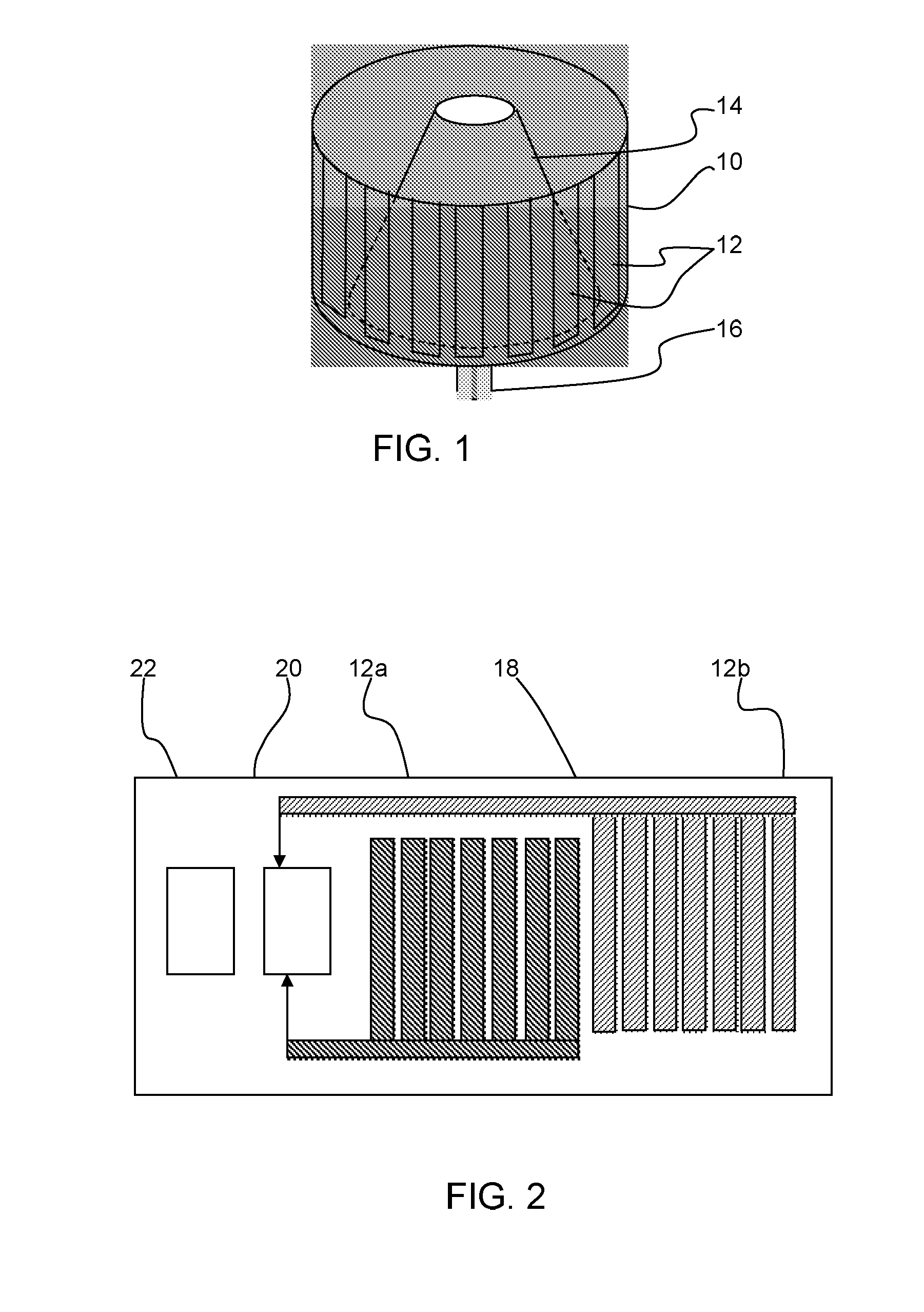
[0022]The invention provides a capacitive liquid level sensor in which a vessel for receiving the liquid has a deflector inside the vessel extending upwardly from the base, and which tapers towards its top. This means the liquid is confined to the edges of the vessel at the bottom of the vessel, which gives improved resolution for small amounts of liquid. The deflector also acts as a baffle resisting liquid flow when there is tilting of the vessel.

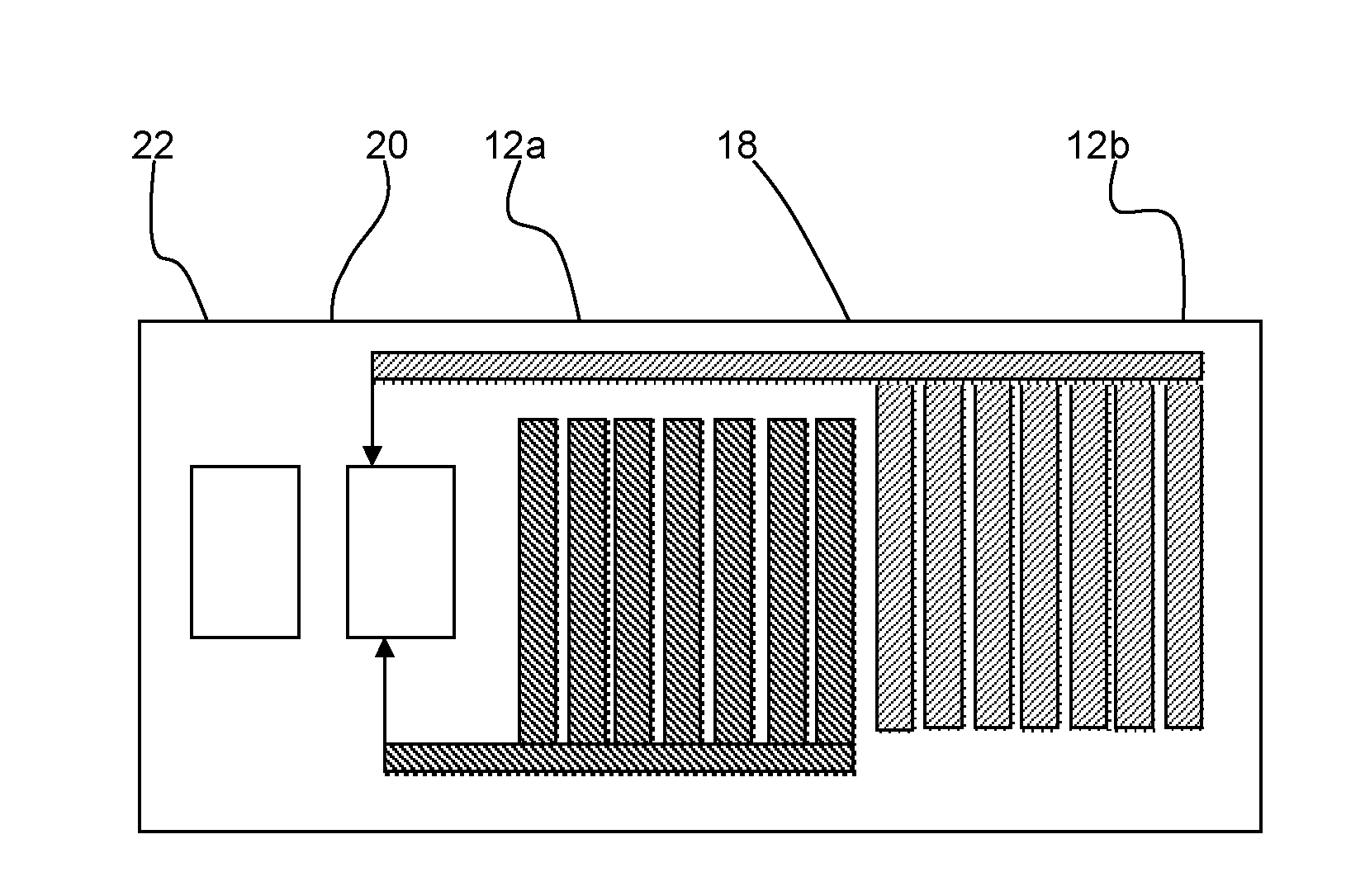
[0023]FIG. 1 shows the vessel of a capacitive fluid sensor of the invention. The capacitive liquid level sensor comprises a container 10 with an even number of surrounding metal electrodes 12 which are elongate and arranged vertically. The electrodes define two opposing capacitor plates. They are segmented into vertical strips to make it possible to bend a PCB carrying the electrodes around the vessel.

[0024]The liquid within the container has a dielectric constant, and the capacitance is proportional to the dielectric constant and hence ge...


PUM


Abstract

A capacitive liquid level sensor in which a vessel for receiving the liquid has a deflector inside the vessel extending upwardly from the base, and which tapers towards its top. This means the liquid is confined to the edges of the vessel at the bottom of the vessel, which gives improved resolution for small amounts of liquid. The deflector also acts as a baffle resisting liquid flow when there is tilting of the vessel.

Description

TECHNICAL FIELD OF THE INVENTION[0001]This invention relates to a capacitive liquid level sensor.BACKGROUND OF THE INVENTION[0002]There are many examples of capacitive liquid level sensors on the market, which use capacitance to detect liquid levels.[0003]A known type of liquid level sensor comprises a cylinder which is to be filled (or part filled) with the liquid to be sensed. Capacitor plate electrodes extend up the outside of the cylinder wall in the form of elongate strips. There is a series of electrodes around the cylinder, which together define a pair of capacitor plates. The capacitance depends on the fluid level in the cylinder, since the liquid influences the dielectric permittivity between the electrodes. The level of the liquid determines the capacitor area over which this permittivity is effective.[0004]This standard capacitive liquid level sensor has two principal disadvantages. The sensor is sensitive to operating angle and in practice it has a limited dynamic range....

Claims


Application Information

Patent Timeline
IPC IPC(8): G01F23/26
CPCG01F23/266G01F23/263G01F23/268
Inventor LEPPARD, MICHAEL JAMES ROBBERT
Owner KONINKLJIJKE PHILIPS NV
Why Eureka
Try Eureka