Method of and apparatus for composing a series of partial images into one image based upon a calculated amount of overlap

a partial image and overlap technology, applied in the field of image input apparatus and image input method, can solve the problems of long input time, difficult to carry, and inability to input the paper face of a document having a large size, and achieve the effect of maintaining the amount of overlap and simple structur

Inactive Publication Date: 2006-12-05
RICOH KK
View PDF8 Cites 22 Cited by
  • Summary
  • Abstract
  • Description
  • Claims
  • Application Information

AI Technical Summary

Benefits of technology

[0011]It is an object of this invention to provide a small sized, inexpensive image input apparatus and image input method which can detect a change in picked up images between a partial image previously picked up and a current partial image by using a simple structure, and which can properly maintain the amount of overlap of the partial images required at the time of image composition.

Problems solved by technology

In an attempt to achieve these demands, conventional flat bed scanners have problems in which it is difficult to carry these and it is also impossible to input the paper face of a document having a large size.
However, the action (operation) for carrying out the scanning with the apparatus made in contact with the paper face is inferior in operability, resulting in a problem of a long input time.
However, problems with this image input apparatus disclosed by this Patent Publication are that the resolution in the input image tends to become insufficient as a whole and that the resolution tends to vary depending on portions thereof located in front the input apparatus and those portions located apart from the input apparatus.
Along with the development of digital image pickup apparatuses with high resolution, the number of pixels in a CCD image pickup element has been remarkably improved; however, these are still insufficient in picking up fine characters and patterns with good reproducibility.
However, on the other hand, there is an increase in the number of partial images to be picked up, and consequently, an increased processing time in the image composing process.
However, such an operation imposes considerable skills and errors on the photographer's side.
However, it is not possible to input the paper face of large size paper, and it is necessary to take into consideration influences from the hand shaking, with the result that the overlapping areas are taken in an excessive manner.
However, the problem with the above mentioned conventional image input apparatus as described in Japanese Patent Application Laid-Open No. 9-261520 is that the orientation angles and positions of the input apparatus with 6 degrees of freedom with respect to a subject need to be detected, with the result that the apparatus becomes bulky and expensive in order to carry out these detections, resulting in an expensive apparatus; therefore, this method is not suitable for a practical use.
Moreover, the size of the overlapping area is determined by using pattern matching from an input image; however, in order to achieve this process, it is necessary to input image at high speeds, with the result that a very expensive image pickup element is required and the apparatus is limited in the usable environments.

Method used


Image

  • Method of and apparatus for composing a series of partial images into one image based upon a calculated amount of overlap
  • Method of and apparatus for composing a series of partial images into one image based upon a calculated amount of overlap
  • Method of and apparatus for composing a series of partial images into one image based upon a calculated amount of overlap

Examples


first embodiment

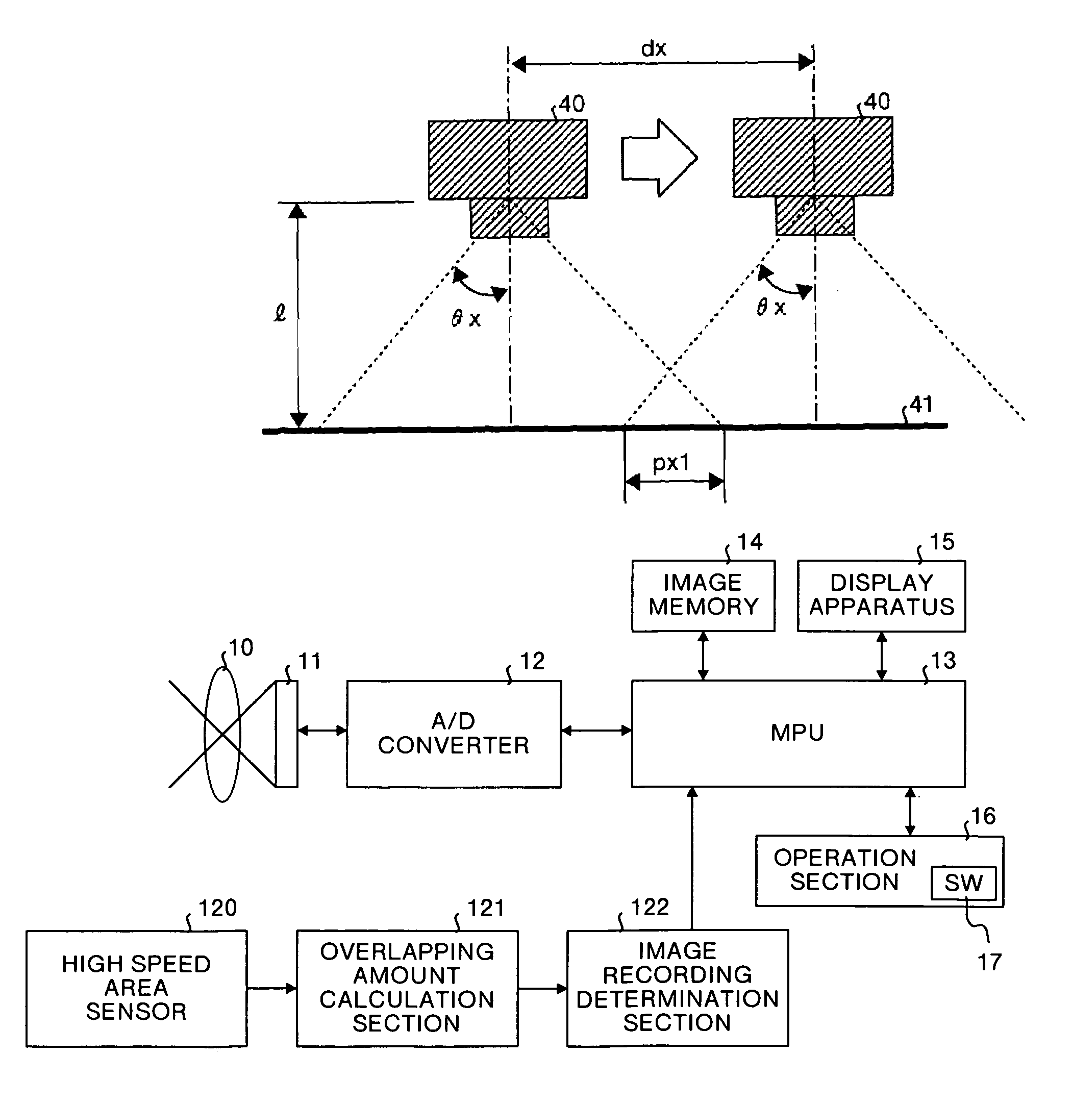
[0054]FIG. 8 is a block diagram that shows the construction of an image input apparatus in accordance with the present invention. In this Figure, reference number 30 represents a relative position detection section for detecting relative positions between a certain period of time in the image input apparatus, reference number 31 represents an overlapping amount calculation section for detecting the amount of overlap (overlapped area) between partial images from the detected value of the relative position detection section 30, and reference number 32 represents an image recording determination section for determining whether or not the current partial image is recordable based upon the amount of overlap calculated by the overlapping amount calculation section 31. Here, the other constituent elements are the same as those shown in FIG. 1; therefore, the same reference numbers are used, and the description thereof is omitted.

[0055]The relative position detection section 30 is constitut...

second embodiment

[0064]FIG. 10 is a block diagram that shows the construction of an image input apparatus in accordance with the present invention. In this Figure, reference number 50 represents an angle detection section for detecting a change in angles between a certain period of time in the image input apparatus, reference number 51 represents an overlapping amount calculation section for detecting the amount of overlap (overlapped area) between partial images from the detected value of the angle detection section 50, and reference number 52 represents an image recording determination section for determining whether or not the current partial image is recordable based upon the amount of overlap calculated by the overlapping amount calculation section 51. Here, the other constituent elements are the same as those shown in FIG. 1; therefore, the same reference numbers are used, and the description thereof is omitted.

[0065]The angle detection section 50 is constituted by, for example, a gyro sensor ...

third embodiment

[0075]FIG. 12 is a block diagram that shows the construction of an image input apparatus in accordance with the present invention. In this Figure, reference number 80 represents an angle detection section for detecting a change in orientation angles between a certain period of time in the image input apparatus, reference number 81 represents a relative position detection section for detecting a relative position of the image input apparatus between a certain period of time, reference number 82 represents an overlapping amount calculation section for detecting the amount of overlap (overlapped area) between partial images from the detected value of the angle detection section 80 or the detected value of the relative positional detection section 81, and reference number 83 represents an image recording determination section for determining whether or not the current partial image is recordable based upon the amount of overlap calculated by the overlapping amount calculation section 82...


PUM


Abstract

The image input apparatus comprises the image pickup unit which optically scans a subject and successively acquires partial images of the subject. The relative change detection unit detects an amount of relative change in position or speed of the image pickup unit between a time when a previous partial image was taken and a time when a current partial image is being taken. The an overlapping amount calculating unit calculates an amount of overlap between the previous partial image and the current partial image based upon the amount of relative change in position or speed detected by the relative change detection unit. The image recording determination unit determines whether or not the current partial image is to be recorded based upon the amount of overlap calculated by the overlapping amount calculating unit.

Description

FIELD OF THE INVENTION[0001]The present invention relates to image input apparatuses such as digital cameras or non contact type handy scanners and image input method. More particularly, this invention relates to the image input apparatus and image input method which can pick up partial images at such timing that the amount of overlap among the partial images is properly, and then composes the partial images into one image.BACKGROUND OF THE INVENTION[0002]Recently, in the portable information terminals, there have been ever increasing demands for inputting various documents, especially in the mobile computer environments. These documents vary in a wide range including A 4 size to those sizes wider than this. In an attempt to achieve these demands, conventional flat bed scanners have problems in which it is difficult to carry these and it is also impossible to input the paper face of a document having a large size. In order to solve these problems, for example, Japanese Patent Applic...

Claims


Application Information

Patent Timeline
Patent Type & Authority Patents(United States)
IPC IPC(8): H04N5/225G06T1/00G06T3/00H04N1/107H04N1/195H04N1/387H04N5/232H04N5/262
CPCH04N1/107H04N1/19594H04N1/3876H04N5/232H04N5/23238H04N1/195H04N2201/0414H04N2201/0436H04N2201/0471H04N2201/04734H04N23/60H04N23/698
Inventor KITAGUCHI, TAKASHIMURATA, NORIHIKOAOKI, SHINSASAKI, SABUROH
Owner RICOH KK
Why Eureka
Try Eureka