Rechargeable battery

a rechargeable battery and battery management technology, applied in the field of rechargeable batteries, can solve the problems of low accuracy of detected pressure value, additional installation space, and unit cells bursting, and achieve the effects of reducing pressure, high accuracy of detected value, and high degree of control freedom and accuracy of battery management system

Inactive Publication Date: 2012-11-01
ROBERT BOSCH GMBH +1
View PDF6 Cites 23 Cited by
  • Summary
  • Abstract
  • Description
  • Claims
  • Application Information

AI Technical Summary

Benefits of technology

[0023]According to an aspect of embodiments of the present invention, in a rechargeable battery, a penetration hole is formed in an electrode terminal and a piezoelectric element is installed in the penetration hole to provide high accuracy of a detected value and detect a change of internal pressure of the rechargeable battery, thereby checking an internal mechanical state thereof. According to another aspect of embodiments of the present invention, the piezoelectric element is installed in the penetration hole of the electrode terminal such that no additional installation space is needed. According to another aspect of embodiments of the present invention, the piezoelectric element detects a decrease of the pressure caused by a rise of the internal pressure and leakage of the electrolyte solution, thereby providing a high degree of control freedom and accuracy of the battery management system.

Problems solved by technology

Particularly, when the internal pressure is increased, the unit cells may explode.
However, when the pressure sensor is installed outside the rechargeable battery, accuracy of the detected pressure value is low.
On the other hand, when the pressure sensor is installed inside the rechargeable battery, additional installation space is required.
Also, the pressure sensor may detect rising of the internal pressure, but may fail to detect a decreasing of the internal pressure.

Method used


Image

  • Rechargeable battery
  • Rechargeable battery
  • Rechargeable battery

Examples


Embodiment Construction

[0030]Aspects of the present invention will be described more fully hereinafter with reference to the accompanying drawings, in which some exemplary embodiments of the present invention are shown. As those skilled in the art would realize, the described embodiments may be modified in various different ways, all without departing from the spirit or scope of the present invention. Accordingly, the drawings and description are to be regarded as illustrative in nature and not restrictive. Like reference numerals designate like elements throughout the specification.

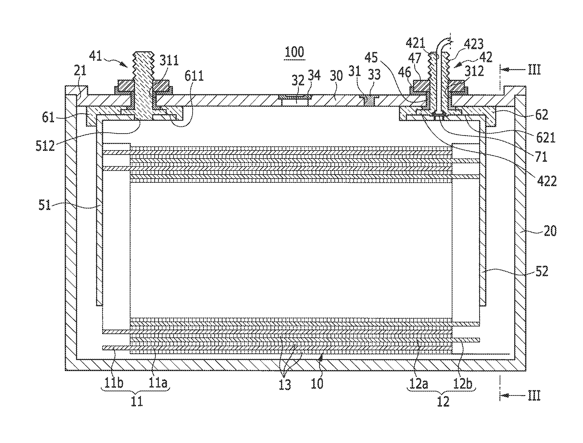
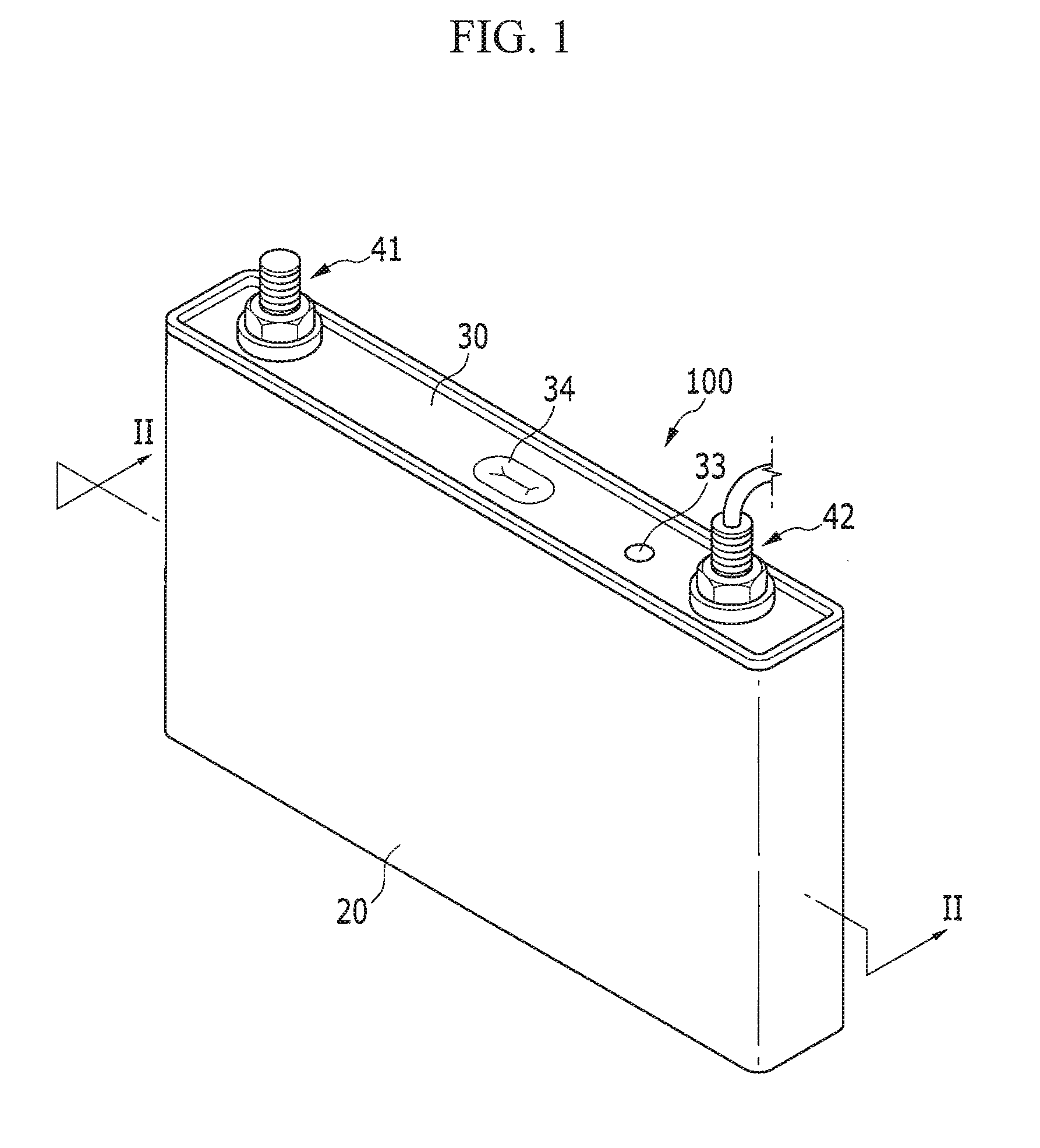
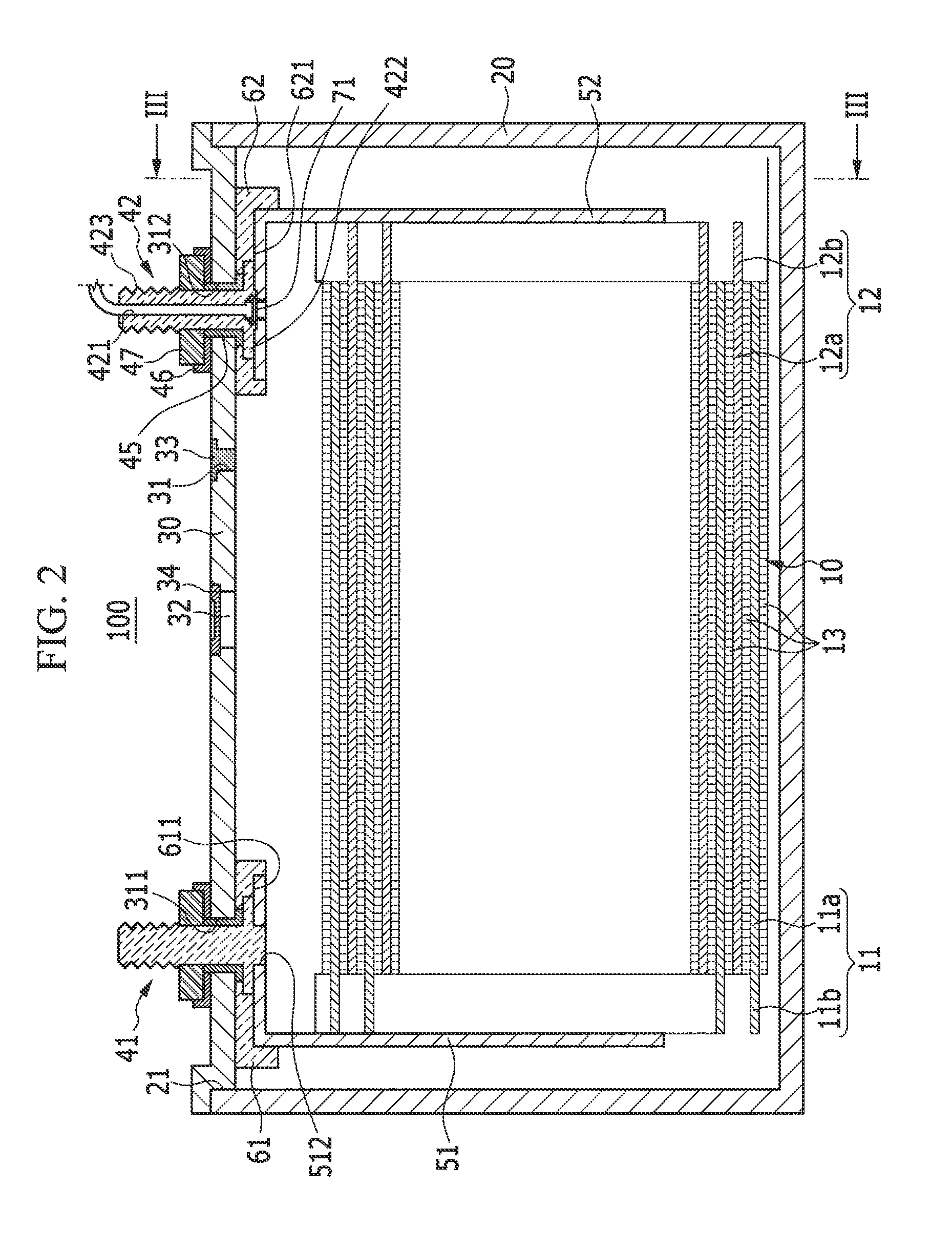
[0031]FIG. 1 is a perspective view of a rechargeable battery 100 according to an exemplary embodiment of the present invention, and FIG. 2 is a cross-sectional view of the rechargeable battery 100, taken at the line II-II of FIG. 1. Referring to FIGS. 1 and 2, the rechargeable battery 100 includes an electrode assembly 10 to be charged and discharged, a case 20 housing the electrode assembly 10 and an electrolyte solution, a c...


PUM

PropertyMeasurementUnit
pressureaaaaaaaaaa
piezoelectricaaaaaaaaaa
voltagesaaaaaaaaaa

Abstract

A rechargeable battery including an electrode assembly including first and second electrodes, and a separator between the first and second electrodes; a case housing the electrode assembly; a cap plate closing an opening of the case; an electrode terminal in a terminal hole of the cap plate and electrically connected to the electrode assembly, the electrode terminal having a penetration hole for connecting an inside and an outside of the case; and a piezoelectric element in the penetration hole, the piezoelectric element configured to detect a change of pressure inside the case and transmit a detection signal to the outside of the case.

Description

CROSS-REFERENCE TO RELATED APPLICATION[0001]This application claims priority to and the benefit of Korean Patent Application No. 10-2011-0039068, filed on Apr. 26, 2011 in the Korean Intellectual Property Office, the entire content of which is incorporated herein by reference.BACKGROUND[0002]1. Field[0003]Aspects of embodiments of the present invention relate to a rechargeable battery.[0004]2. Description of the Related Art[0005]Unlike a primary battery, a rechargeable battery can repeatedly perform charging and discharging. A small-capacity rechargeable battery is typically used in a portable small-sized electronic device such as a mobile phone, a notebook computer, and a camcorder, and a large-capacity rechargeable battery may be used as a power supply for driving a motor, such as a motor for an electric vehicle or a hybrid electric vehicle.[0006]For example, a rechargeable battery having small capacity may be used for a unit cell, and a plurality of rechargeable batteries, or uni...

Claims


Application Information

Patent Timeline
Patent Type & Authority Applications(United States)
IPC IPC(8): H01M10/48H01M50/533H01M50/538
CPCH01M2/263H01M10/48H01M2/307Y02E60/10H01M50/538H01M50/561H01M50/533G01R31/36G01L9/00H01M50/543H01M50/531H01M50/567H01M50/502
Inventor KIM, DUK-JUNG
Owner ROBERT BOSCH GMBH
Why Eureka
Try Eureka