Electromagnetic relay

a technology of electromagnetic relays and relays, applied in electromagnetic relays, electrical apparatus, electromagnetical relay details, etc., can solve problems such as power consumption increase and malfunction of contact devices, and achieve excellent impact resistance

Active Publication Date: 2015-05-07
ORMON CORP
View PDF7 Cites 8 Cited by
  • Summary
  • Abstract
  • Description
  • Claims
  • Application Information

AI Technical Summary

Benefits of technology

[0069]According to the present invention, since the movable iron core is reduced in weight and force of inertia is small, even though an impact force is applied in an axial direction of the movable shaft, the whole movable part becomes difficult to be displaced, and thus an electromagnetic relay which is unlikely to malfunction is obtained. Furthermore, since it is unnecessary to increase an application voltage for prevention of malfunction, there is an advantage that an energy-saving electromagnetic relay which consumes less electric power is obtained.
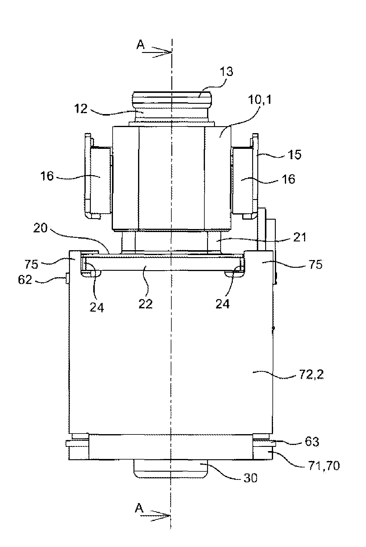
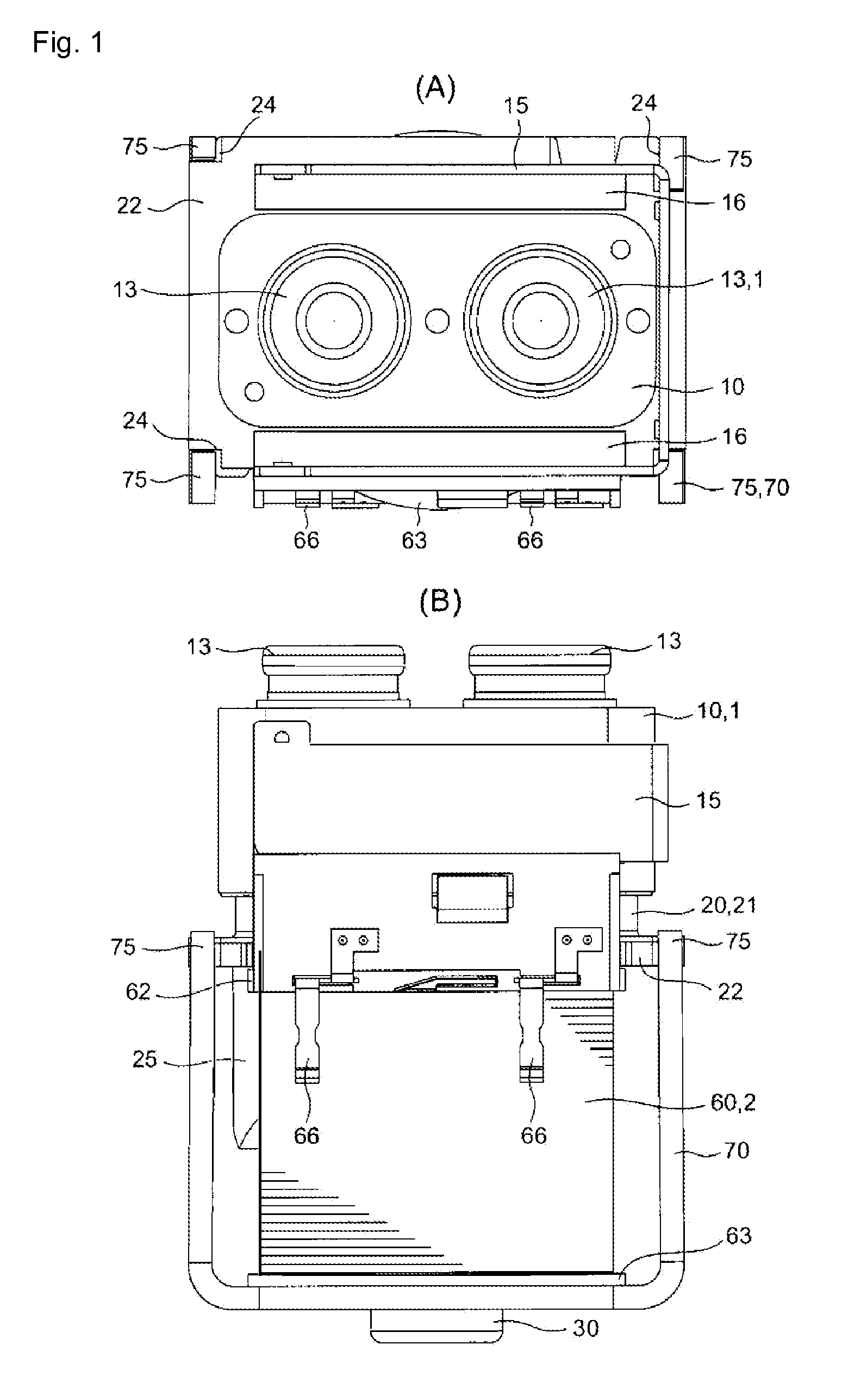
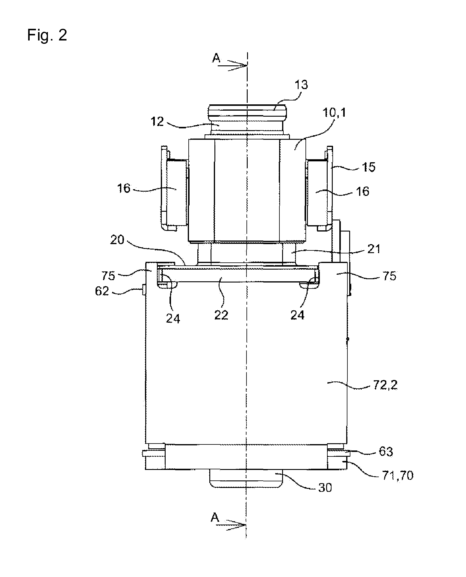
[0007]An electromagnetic relay is further provided as including a movable iron core arranged to move up and down within an axial center hole of a solenoid formed by winding a coil, a contact switch wherein an upper end surface of the movable iron core attaches to and detaches from a lower end surface of a fixed iron core arranged in the axial center hole according to magnetization and demagnetization of the solenoid, and a movable contact attaches to and detaches from a fixed contact by a movable shaft which reciprocates along with the movable iron core, a bored portion provided in an opening edge portion of a lower end surface of the movable iron core; and a sliding portion comprising an exterior circumferential surface of the movable iron core, the sliding portion disposed in an auxiliary yoke having a cylindrical shape which is provided in a yoke, where the sliding portion always abuts the auxiliary yoke during the up and down movement; and where a height dimension of the sliding portion is at least equal to or larger than a plate thickness dimension of the yoke.
[0007]An electromagnetic relay is further provided as including a movable iron core arranged to move up and down within an axial center hole of a solenoid formed by winding a coil, a contact switch wherein an upper end surface of the movable iron core attaches to and detaches from a lower end surface of a fixed iron core arranged in the axial center hole according to magnetization and demagnetization of the solenoid, and a movable contact attaches to and detaches from a fixed contact by a movable shaft which reciprocates along with the movable iron core, a bored portion provided in an opening edge portion of a lower end surface of the movable iron core; and a sliding portion comprising an exterior circumferential surface of the movable iron core, the sliding portion disposed in an auxiliary yoke having a cylindrical shape which is provided in a yoke, where the sliding portion always abuts the auxiliary yoke during the up and down movement; and where a height dimension of the sliding portion is at least equal to or larger than a plate thickness dimension of the yoke.
[0007]An electromagnetic relay is further provided as including a movable iron core arranged to move up and down within an axial center hole of a solenoid formed by winding a coil, a contact switch wherein an upper end surface of the movable iron core attaches to and detaches from a lower end surface of a fixed iron core arranged in the axial center hole according to magnetization and demagnetization of the solenoid, and a movable contact attaches to and detaches from a fixed contact by a movable shaft which reciprocates along with the movable iron core, a bored portion provided in an opening edge portion of a lower end surface of the movable iron core; and a sliding portion comprising an exterior circumferential surface of the movable iron core, the sliding portion disposed in an auxiliary yoke having a cylindrical shape which is provided in a yoke, where the sliding portion always abuts the auxiliary yoke during the up and down movement; and where a height dimension of the sliding portion is at least equal to or larger than a plate thickness dimension of the yoke.
[0069]According to the present invention, since the movable iron core is reduced in weight and force of inertia is small, even though an impact force is applied in an axial direction of the movable shaft, the whole movable part becomes difficult to be displaced, and thus an electromagnetic relay which is unlikely to malfunction is obtained. Furthermore, since it is unnecessary to increase an application voltage for prevention of malfunction, there is an advantage that an energy-saving electromagnetic relay which consumes less electric power is obtained.

Problems solved by technology

However, in the contact device, when impact force is externally applied in an axial direction of the cylindrical movable shaft during non-excitation, for example, there is a possibility that the movable contact comes into contact with the fixed contact due to the force of inertia of the whole movable parts and thus the contact device malfunctions.
For this reason, there is a problem that a high application voltage needs to be applied to drive the movable parts and thus power consumption increases.

Method used


Image

  • Electromagnetic relay
  • Electromagnetic relay
  • Electromagnetic relay

Examples


example 1

[0050]Regarding an impact resistance of the electromagnetic relay according to the present invention, a calculated moving distance and a calculated impact resistance value are obtained, and an actually measured impact resistance value is also obtained. The result is shown in FIG. 8.

[0051]Examples 1 and 2 illustrated in FIG. 8 were cases where weight reduction was achieved by providing an annular groove portion in an exterior circumferential surface of a movable iron core, and a spring constant of a contact spring was fixed. A comparative example was a case where the annular groove portion was not provided and the spring constant of the contact spring varied.

[0052]The calculated moving distance and calculated impact resistance value are calculated using the following formula on the assumption that total energy before a collision occurs and total energy in a state in which a movable part moved to a bottom dead center of a spring are equal to each other.

½.(ks1+F0)x1+½.mv12+mgx1=½.(kx2+...

example 2

[0065]For examples 1 and 2, the annular groove portion is provided in the exterior circumferential surface of the movable iron core which weighs 0.86 m and 0.64 m, respectively. For the comparative example, the annular groove portion is not provided in the exterior circumferential surface of the movable iron core and weighs m. For the various examples, operation sound and return sound are measured individually. Measurement results are shown below.

Operation sound (dB)Return sound (dB)Example 158.551.0Example 255.150.6Comparative Example63.658.5

[0066]It was found from the above measurement results that examples 1 and 2 exhibited decreases of 5.1 dB and 8.5 dB in the operation sound, respectively compared to the comparative example, and decreases of 7.5 dB and 7.9 dB in the return sound, respectively compared to the comparative example.

[0067]Accordingly, it was confirmed that the sound is reduced as the weight of the movable iron core is decreased.

[0068]The present invention is not lim...


PUM


Abstract

An electromagnetic relay includes a movable iron core arranged to move up and down within a center hole of an electromagnet unit formed by winding a coil, and a contact switch where an upper end surface of the movable iron core attaches to and detaches from a lower end surface of a fixed iron core arranged in the center hole according to magnetization and demagnetization of the electromagnet unit and a movable contact attaches to and detaches from a fixed contact by a movable shaft which reciprocates along with the movable iron core where the movable iron core includes a sliding portion which always abuts an auxiliary yoke disposed within a yoke, and where a height dimension of the sliding portion is at least equal to or larger than a plate thickness dimension of the yoke.

Description

CROSS REFERENCE TO RELATED APPLICATION[0001]This application, filed under 35 U.S.C. 371, is the U.S. national phase of International Patent Application Number PCT / JP2012 / 063778 filed on 29 May 2012 which claims priority to Japanese Patent Application Number 2011-122041 filed on 31 May 2011, all of which said applications are herein incorporated by reference in their entirety.TECHNICAL FIELD[0002]The present invention relates to an electromagnetic relay and more particularly to an electromagnetic relay excellent in impact resistance.BACKGROUND ART[0003]In a conventional electromagnetic relay, there is a contact device including a fixed terminal provided with a fixed contact, a movable terminal provided with a movable contact configured to attach to and detach from the fixed contact, a cylindrical movable shaft having an end to which the movable contact is fixed, a movable iron core fixed to the other end of the movable shaft, a fixed iron core which is externally inserted into the mo...

Claims


Application Information

Patent Timeline
Patent Type & Authority Applications(United States)
IPC IPC(8): H01H50/20
CPCH01H50/20H01H50/22H01H51/065H01H2050/025H01H2050/446
Inventor KAWAGUCHI, KENSUKEHIROKI, KAZUCHIKAYOSHIHARA, IKUHIROYAMAKITA, TOMOHIROAYADO, HARUKIYOSHIYAMA, TOMOMIIWASAKA, HIROYUKI
Owner ORMON CORP
Why Eureka
Try Eureka