Antenna module having a transmitting and receiving antenna element

a technology of antenna elements and antenna modules, applied in the direction of antenna details, antenna adaptation in movable bodies, antennas, etc., can solve the problems of high cost, and achieve the effect of cost-effective and compa

Active Publication Date: 2015-05-07
KATHREIN AUTOMOTIVE GMBH +1
View PDF10 Cites 47 Cited by
  • Summary
  • Abstract
  • Description
  • Claims
  • Application Information

AI Technical Summary

Benefits of technology

[0010]An aspect of the invention aims to overcome the disadvantages of the prior art and to provide an antenna module for a vehicle which can be mounted as an installation part in the roof region

Problems solved by technology

This embodiment of an antenna module has the following disadvantages:1. two circuit boards are used, which gives rise to the need for high-frequency-compatible connectors for two circuit boards,2. radiation of the external antennas into the passenger compartment is possible,3. large circuit bo

Method used


Image

  • Antenna module having a transmitting and receiving antenna element
  • Antenna module having a transmitting and receiving antenna element
  • Antenna module having a transmitting and receiving antenna element

Examples


first embodiment

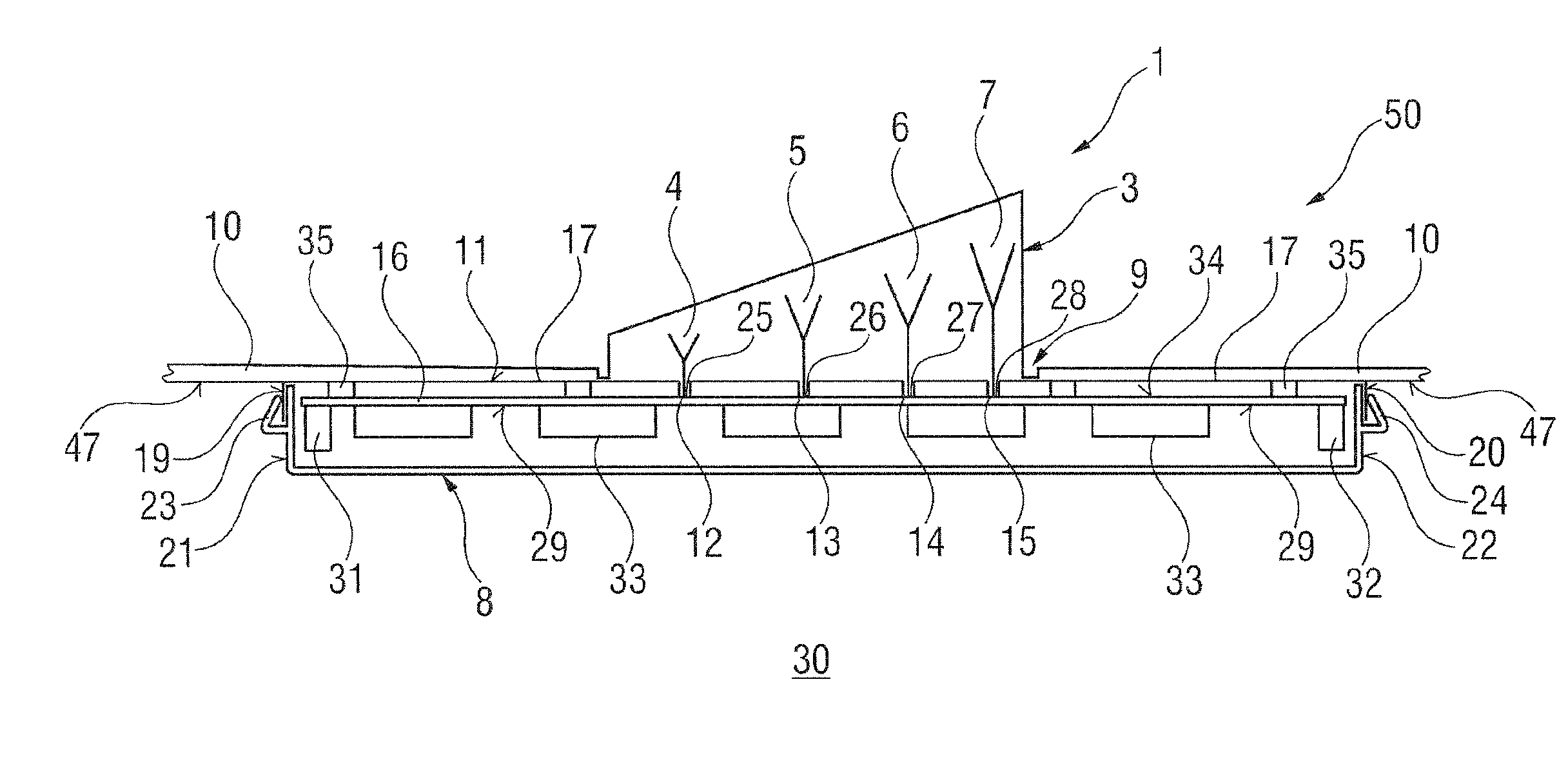
[0038]FIG. 1 shows a basic sketch of an antenna module 1 according to the invention. The antenna module 1 is intended for a motor vehicle 50 and is arranged on a vehicle roof 10. A fin-shaped outer cover 3 projects out of the vehicle roof 10, from an opening 9 in the vehicle roof 10. This outer cover 3 is at the same time a protective sheath for the antenna elements 4, 5, 6 and 7 arranged under the protective sheath. Feed-in points 25, 26, 27 and 28 of the antenna elements 4, 5, 6 and 7 are connected electrically to an antenna circuit board 16 via feedthroughs 12, 13, 14 and 15. The antenna circuit board 16 is accommodated in an antenna box which is closed on all sides, wherein the antenna box 8 is connected in an electrically conductive fashion to an inner side 47 of the vehicle roof 10.

[0039]For this purpose, the antenna box 8 has an electrically conductive upper part 17 which is electrically connected to the inner side 47 of the vehicle roof 10. This electrically conductive upper...

second embodiment

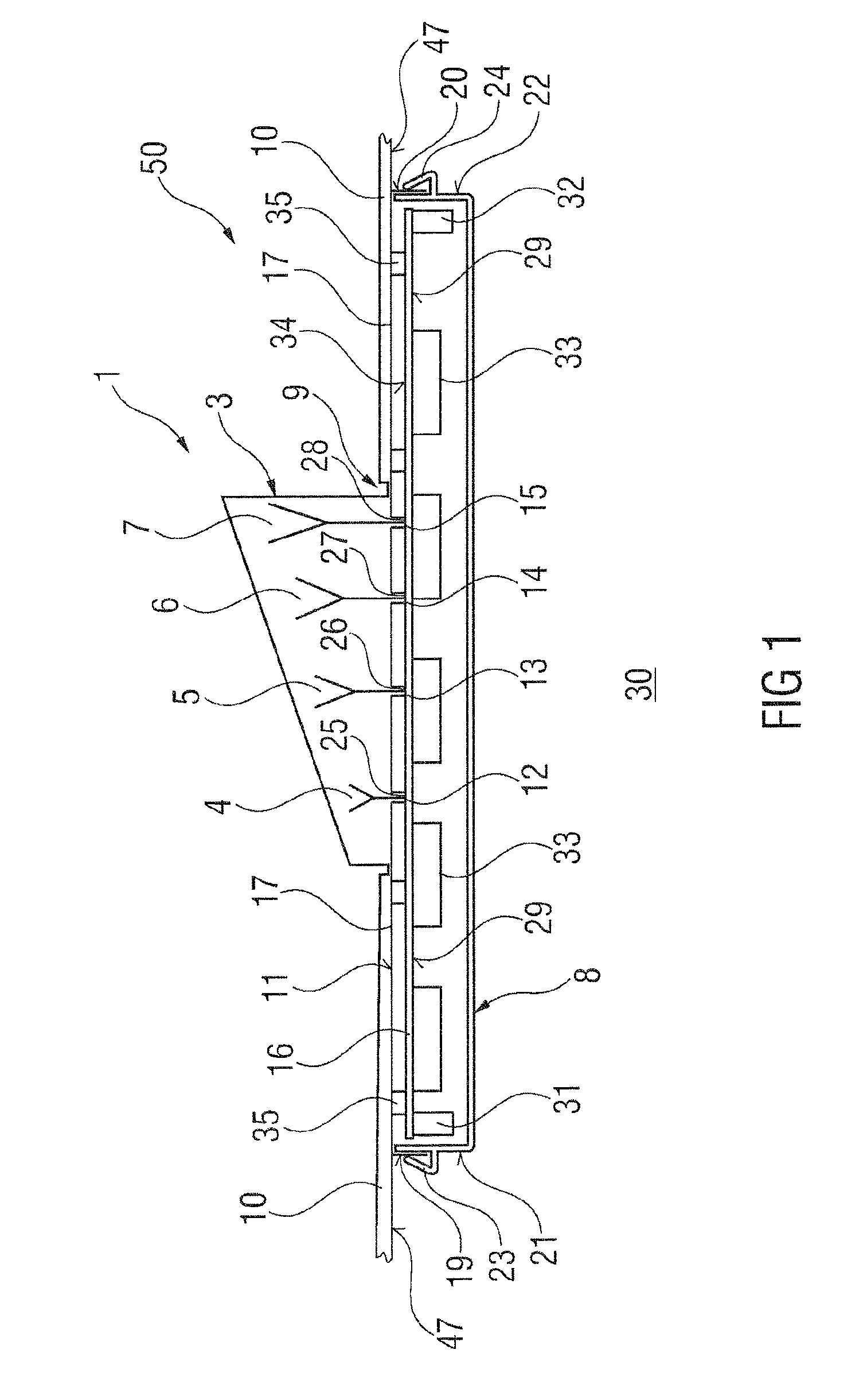
[0043]FIG. 2 shows a basic sketch of an antenna module 2 according to the invention. Components with the same functions as in FIG. 1 are characterized by the same reference symbols and are not mentioned specially.

[0044]The difference between the second embodiment of the invention compared to the first embodiment of the invention which is shown in FIG. 1 is that shielding plates 33 are provided not only on the lower side 29 of the antenna circuit board 16 but shielding chambers 43 and 44 are additionally arranged on the upper side 34, said shielding chambers 43 and 44 having circuits which interact with the feed-in points 25, 26, 27 or 28 of the antenna elements 4, 5, 6 or 7.

[0045]FIG. 3 shows a schematic perspective view of one of the antenna modules 1 according to one of the preceding embodiments of the invention, wherein the antenna module 1 is plugged together in one piece from three areas. An upper area has the already mentioned outer cover 3, with which the antenna module 1 whi...


PUM


Abstract

A one-piece antenna module, has at least one outside receiving and/or transmitting antenna element under an outer cover. The one-piece antenna module has an antenna box, which has no or few inside internal antennas and which surrounds the electronic circuits that interact with the antenna elements. The outer cover is detachably fastened to the antenna box and can be attached so as to protrude from an opening in the vehicle roof. The antenna box is closed on all sides and can be attached below the vehicle roof by a metal top side. The metal closed top side has feed-throughs for the outside antenna elements. The outside antenna elements in the outer cover are electrically coupled to the circuits inside the antenna box closed on all sides by the feed-throughs. Thus, a compact installation part is obtained, which provides complete shielding between an antenna part and a transceiver part.

Description

CROSS REFERENCE TO RELATED APPLICATIONS[0001]This application is the U.S. National Phase Application of PCT / EP2013 / 059985, filed May 15, 2013, which claims priority to German Patent Application No. 10 2012 208 303.0, filed May 16, 2012, the contents of such applications being incorporated by reference herein.FIELD OF THE INVENTION[0002]The invention relates to a one-piece antenna module having at least one transmitting antenna element and at least one receiving antenna element. The antenna module has an outer cover for external antenna elements. An antenna box comprises electronic circuits which interact with the antenna elements. The outer cover is detachably secured to the antenna box. The outer cover can be attached through an opening in a vehicle roof in such a way that it projects out of the vehicle roof.BACKGROUND OF THE INVENTION[0003]Document EP 1 903 632 B1, which is incorporated by reference, discloses an antenna module, in particular as a central transmitting and / or recei...

Claims


Application Information

Patent Timeline
IPC IPC(8): H01Q1/32H01Q1/24
CPCH01Q1/241H01Q1/3275H01Q1/1214
Inventor CHAKAM, GUY-AYMARSCHILLMEIER, GERALDMIERKE, FRANKVOGT, GERHARD
Owner KATHREIN AUTOMOTIVE GMBH
Why Eureka
Try Eureka