Battery operated electric motor in a work apparatus

a work apparatus and battery technology, applied in the field of electric motors, can solve the problems of inability to use further operating signals of the motor, large electronic complexity of operating an electronically commutated motor, and inability to accurately determine the rotational position of the motor, etc., and achieve the effect of accurate rotational position

Active Publication Date: 2015-02-03
ANDREAS STIHL AG & CO KG
View PDF16 Cites 0 Cited by
  • Summary
  • Abstract
  • Description
  • Claims
  • Application Information

AI Technical Summary

Benefits of technology

[0009]The electric motor of the invention includes an arrangement of field windings for driving the rotor with an electric motor, wherein the field windings are successively alternately connected to an energy source in such a manner that torque acts which drives the rotor. A potential point is provided at each winding circuit chain; the voltage of the potential point is supplied to an input of an evaluation unit via an adaptation device. The adaptation device is switchable and can be operated in two adaptation stages. For switching, a drive circuit, which operates in dependence upon the rotational position of the rotor, is provided and switches the adaptation device into a first adaptation stage with high sensitivity or into a second adaptation stage with low sensitivity in dependence upon the rotational position of the rotor of the electric motor. Thus, it is ensured that the very high generator voltage of the rotating electric motor can be applied via one and the same, expediently analog, input of the evaluation unit as the load voltage which can be tapped off at the potential point in the case of load and which may be lower than the generator voltage by orders of magnitude. The potential point is—by means of the adaptation device—connected to only one analog input of the evaluation unit via only one line. As a result, a simply configured processor with only few analog inputs, which is cost effective, compact and has only low power consumption, can be used as the evaluation unit. The adaptation device is always switched from the first adaptation stage with, for example, high sensitivity into the second adaptation stage with, for example, low sensitivity when the potential at the potential point changes from the load voltage to the generator voltage. As a result of the adaptation device, which according to the invention is switched in a manner correct in terms of rotational position by the drive circuit, very different signals can be transmitted on one signal line and applied to just a single input with little circuit complexity.
[0014]The operating signals, such as a load voltage and induced generator voltage, that are to be tapped off at a phase connection, are supplied to the evaluation unit via a common adaptation device, such that only one input is necessary for both operating signals. For switching the adaptation device, it is provided that when a control signal output by a control unit to the electronic commutator is present, the switching is effected from a first adaptation stage into a second adaptation stage, wherein the control signal is initiated in dependence upon the switching state of the switching elements that are arranged between the phase connections and the energy source. The use of the control signals that switch the switching elements of the commutator for switching the adaptation device can be implemented in a simple manner and ensures switching from one adaptation stage into the other, and vice versa, accurately in terms of rotational position.

Problems solved by technology

Processors having a plurality of inputs, in particular analog inputs, are cost intensive and require a lot of space.
The electronic complexity for operating an electronically commutated motor is considerable; the microprocessors used already process a multiplicity of supplied signals, which is why the use of further operating signals of the motor is often problematic or not possible without the replacement of the processor with a larger and more cost-intensive processor with more analog inputs.

Method used


Image

  • Battery operated electric motor in a work apparatus
  • Battery operated electric motor in a work apparatus
  • Battery operated electric motor in a work apparatus

Examples


Embodiment Construction

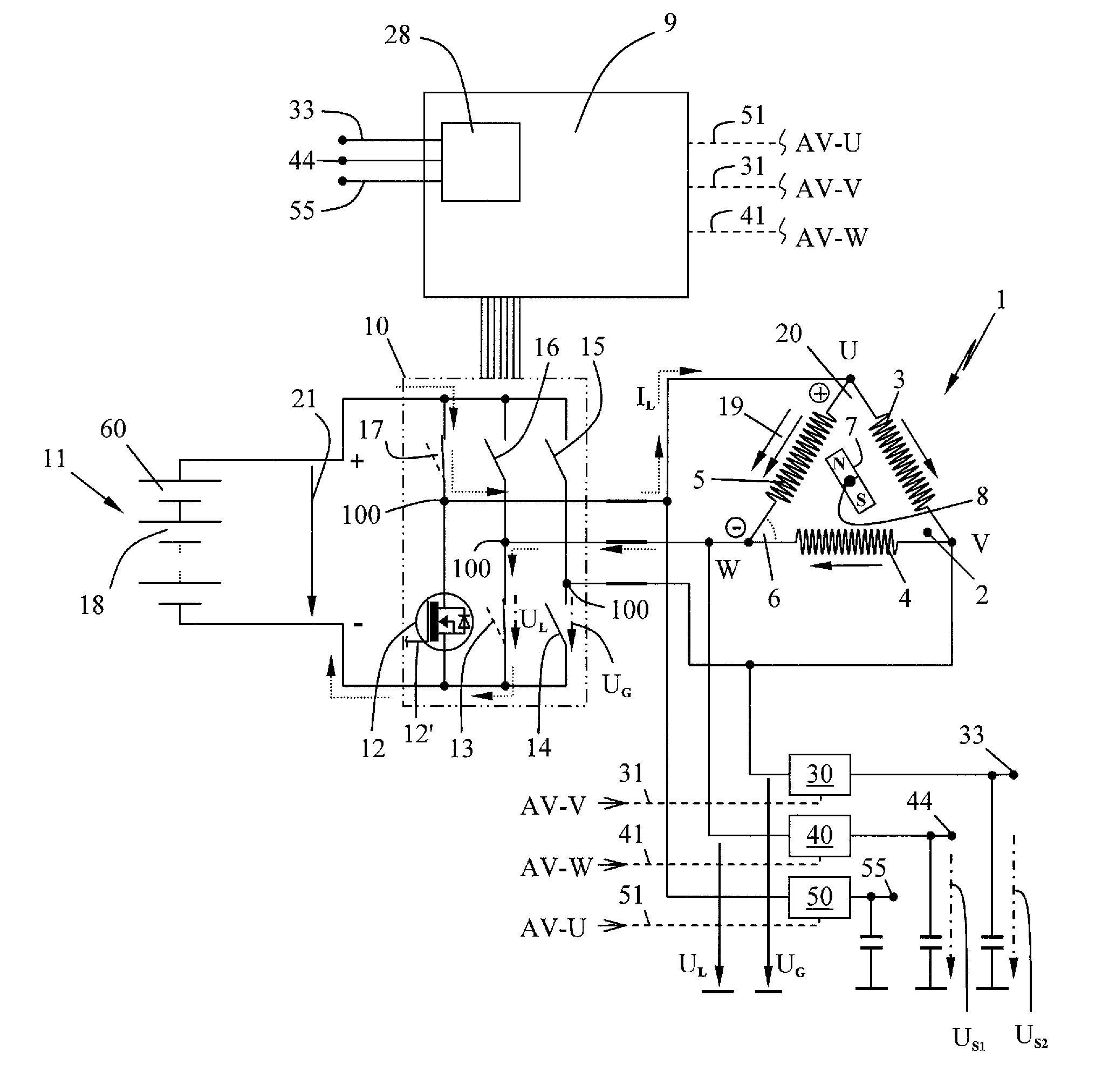
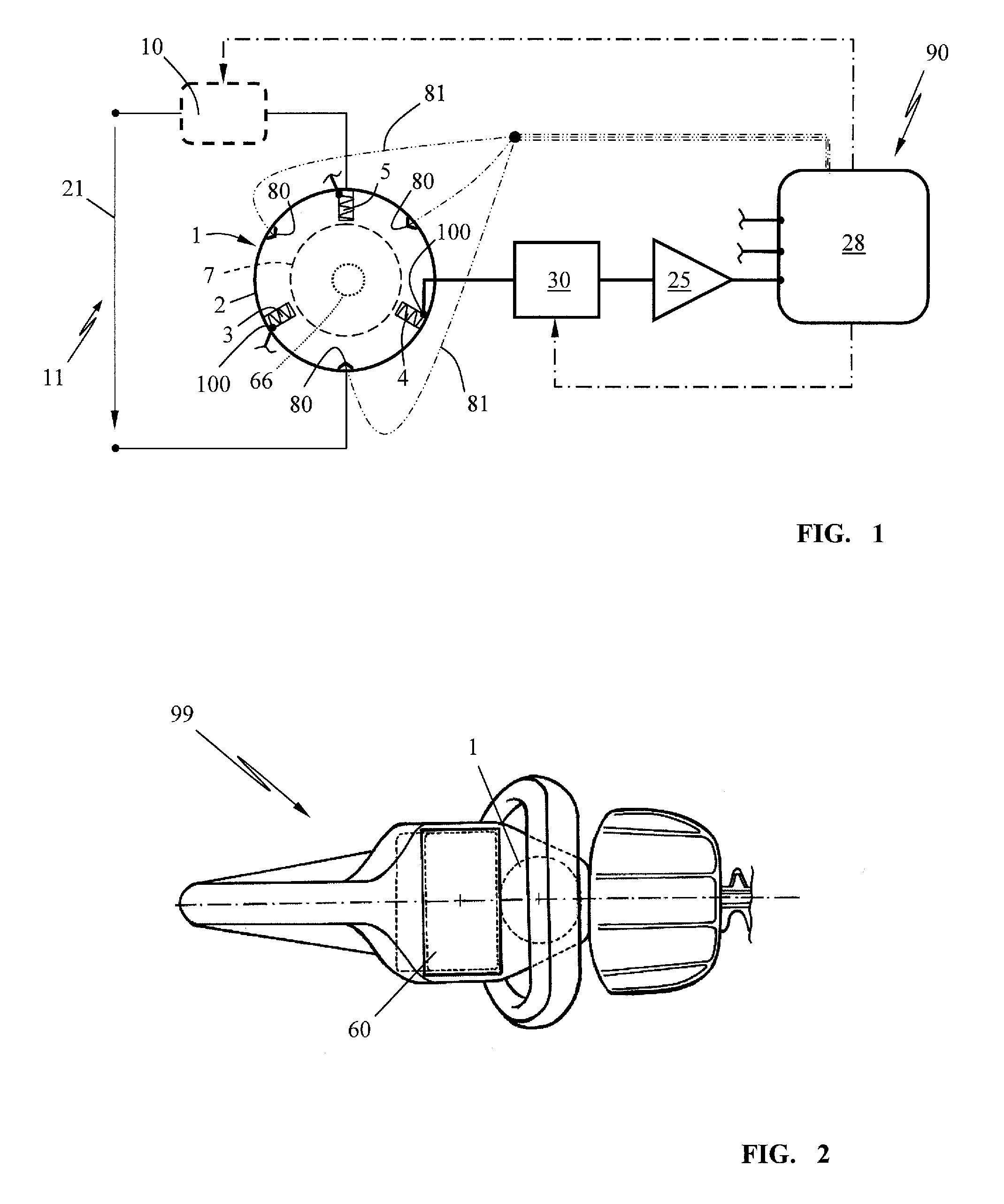
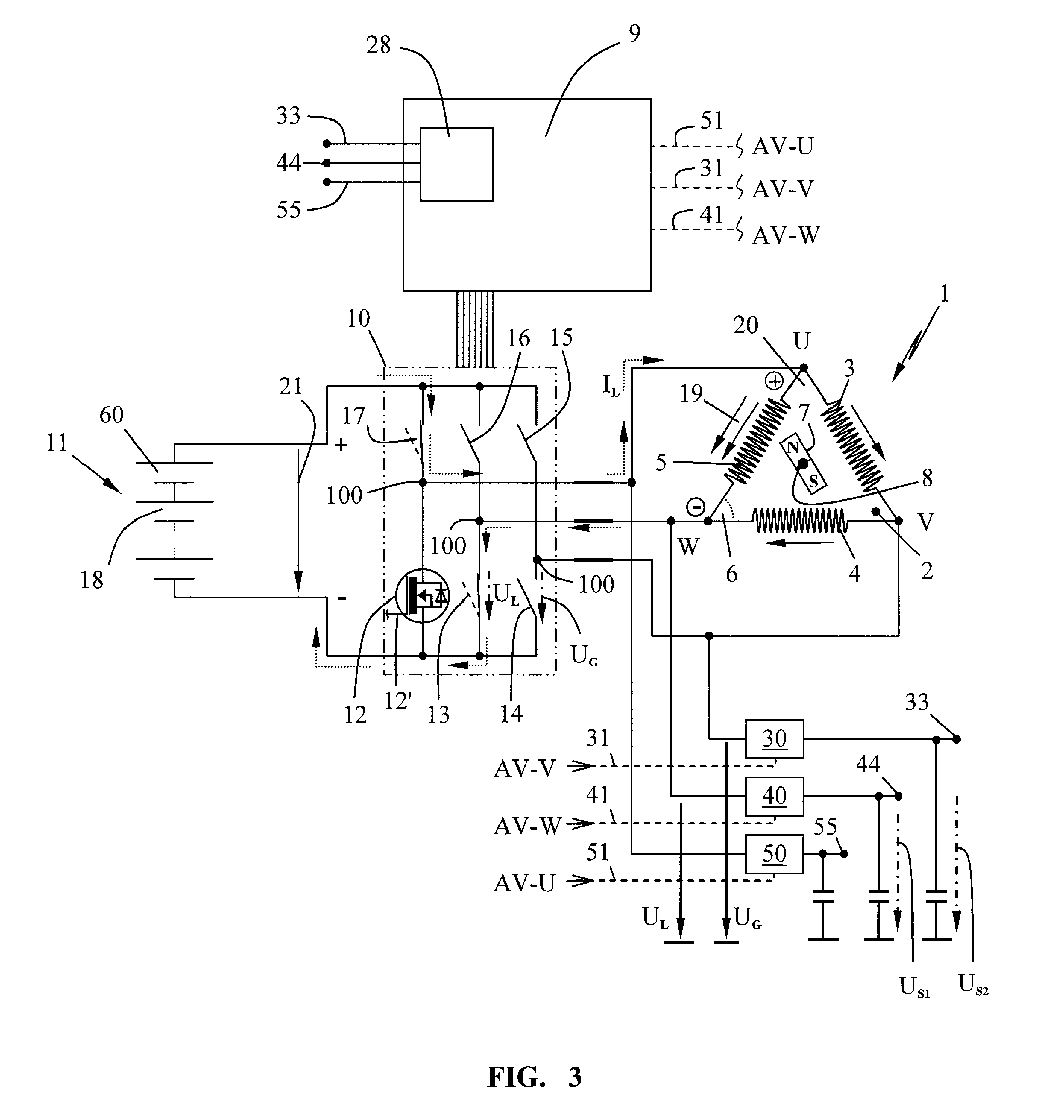
[0027]FIG. 1 shows the principle of the inventive concept on the basis of a schematic. A rotor 7 rotates in a stator 2 of an electric motor 1, wherein the electric motor 1 can be a DC motor (direct current motor) with or without brushes or carbon. The energy source 11 illustrated is a battery block 60 (FIG. 2) and provides a DC voltage as supply voltage 21; a rated voltage of 36 to 42 V is expediently provided depending on the charge state of the battery block.

[0028]The stator 2 of the electric motor 1 has a plurality of windings (3, 4, 5) for generating a rotating field that exerts a driving torque 24 on the rotor 7. In one simple embodiment of a DC motor, the supply voltage 11 is applied to the windings (3, 4, 5) via a mechanical commutator 66, wherein the commutator 66 with rotation of the rotor 7 energizes only the windings assigned to the particular rotational position, as a result of which the rotor 7 is driven in the rotational direction. The current through a winding can be ...


PUM


Abstract

An electric motor includes an arrangement of windings provided for driving the rotor, with the windings being connected to an energy source to develop torque which drives the rotor. The electric circuits of corresponding ones of the windings each have a potential point, the voltage (UL, UG) of which is supplied to an evaluation unit via an adaptation device. The adaptation device can be operated in two switchable adaptation stages and is connected to a drive circuit that operates in dependence upon the rotational position of the rotor. The drive circuit switches the adaptation device into the first stage having a high sensitivity or into the second stage having a low sensitivity in dependence upon the rotational position of the rotor of the motor, such that the number of required analog inputs at a microprocessor in the evaluation unit can be kept low.

Description

CROSS REFERENCE TO RELATED APPLICATION[0001]This application claims priority of German patent application no. 10 2011 106 578.8, filed Jun. 16, 2011, the entire content of which is incorporated herein by reference.FIELD OF THE INVENTION[0002]The invention relates to an electric motor as a drive motor in a work apparatus, especially in a handheld work apparatus such as an electric chain saw, an electric hedge trimmer, an electric brushcutter, an electric blower, an electric cut-off machine or the like.BACKGROUND OF THE INVENTION[0003]Battery operated direct current motors are increasingly being used as a drive in handheld work apparatus such as, for example, chain saws, hedge trimmers, brushcutters, blowers, cut-off machines or the like.[0004]In order to be able to use lightweight, high powered electric motors, a substantial electronic outlay has to be implemented. The electric motors are operated close to their maximum power range, which is why sophisticated electronic monitoring is...

Claims


Application Information

Patent Timeline
Patent Type & Authority Patents(United States)
IPC IPC(8): H02P1/00H02P6/00H02P27/06
CPCH02P6/00
Inventor WICHERT, RENELIEBHARD, GERNOTSAEMANN, RUDOLF
Owner ANDREAS STIHL AG & CO KG
Why Eureka
Try Eureka