
Dual Band Smart Patch Antenna for Satellite Communication

a satellite communication and patch antenna technology, applied in the field of antennas, can solve the problems of difficult optimization of smart antennas for particular functions, complex smart antennas, and difficult optimization of smart antennas, and achieve the effects of compact structure, cost saving and effective us

Inactive Publication Date: 2016-09-22
TIONESTA
View PDF4 Cites 0 Cited by
  • Summary
  • Abstract
  • Description
  • Claims
  • Application Information

AI Technical Summary

Benefits of technology

The present invention offers a small, affordable, high-quality antenna optimized for communication with wireless satellites. It is suitable for a variety of products like satellite communications access points and phones. The invention addresses the problem of bulky antennas and provides a solution for improved efficiency and compactness. The technical effects of the invention include improved signal quality, cost-effectiveness, and versatility in use. The invention can be embodied in different forms and may have changes made to the specifics described.

Problems solved by technology

However, traditionally smart antennas have faced several disadvantages.
For example, smart antennas can be very complex, which makes optimizing a smart antenna for a particular function tedious.
Furthermore, the complexity results in a larger sized antenna and increased cost of the smart antenna.
These disadvantages become magnified in the consumer device marketplace where consumers desire small and attractive communications devices and universal access.
However, optimizing a smart antenna for this frequency range requires much experimentation to find the optimal antenna array orientations.

Method used


Image

  • Dual Band Smart Patch Antenna for Satellite Communication
  • Dual Band Smart Patch Antenna for Satellite Communication
  • Dual Band Smart Patch Antenna for Satellite Communication

Examples


Embodiment Construction

[0017]The present invention relates to an antenna, particularly to a dual band tuned for both 1.6 GHz and 2.5 GHz compact low cost smart antenna for satellite communications use. A smart antenna can steer its main beams towards desired locations by constructive interference while also destructively interfering with undesired signals. Smart antennas are a key technological development in wireless communications that increases the capacity and efficiency of antennas. The preferred embodiment of the present invention is able to focus a beam in 25 different directions in a hemisphere with a 3 decibel loss in gain.

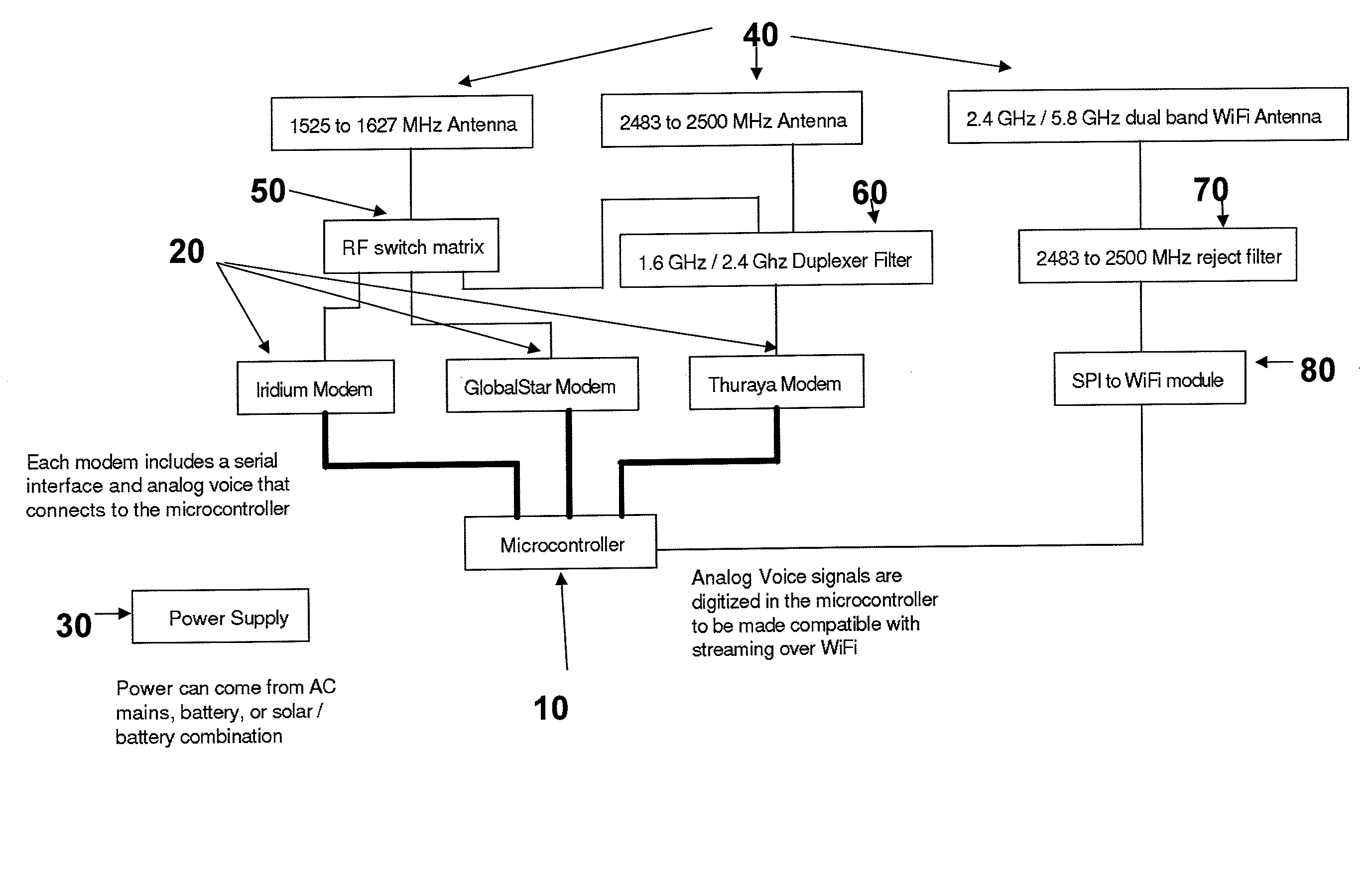
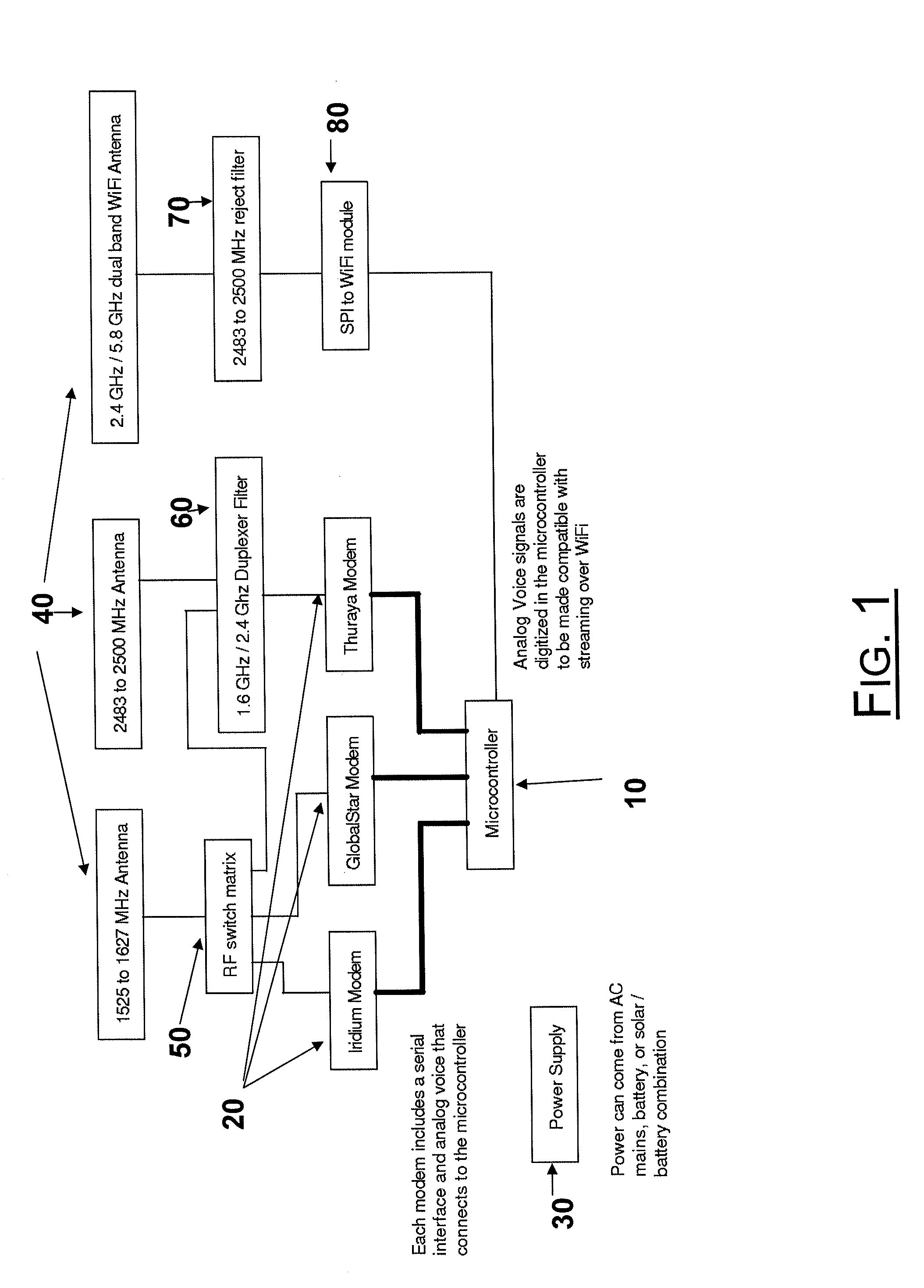
[0018]Turning to FIG. 1, which is a block diagram of one particular embodiment of the invention showing its major components. In this embodiment the microcontroller 10 is connected to the satellite modem 20. The microcontroller 10, which can be any commercially available microcontroller with a memory that is capable of receiving machine readable code. The microcontroller 10 pro...


PUM


Abstract

The present invention offers and effective, compact, cost efficient, smart antenna optimized for the 1.6 GHz and 2.5 GHz frequency range. The present invention provides a compact satellite bridge device optimized to communicate with wireless satellites without the need for bulky antennas. The antenna of the present invention can be used in a variety of products, such as satellite communications access points and satellite phones.

Description

BACKGROUND OF THE INVENTION[0001]1. Field of the Invention[0002]The present invention relates to an antenna, particularly to a dual band tuned for both 1.6 GHz and 2.5 GHz compact low cost smart antenna for satellite and other wireless communications use.[0003]2. Description of Related Art[0004]Smart antennas, also known as antenna arrays, are a technology using two or more individual antenna elements to form an antenna array. The smart antenna changes the array pattern in response to the signal environment to improve the reception of the signal. The smart antenna works by adjusting the phase and amplitude of the signals received by each antenna element. The antenna gain is maximized in the desired direction and the gain is minimized or suppressed direction of interference signals. In essence the smart antenna uses the individual antenna elements to focus and steer the beam of the received signal. A smart antenna has the potential to increase the range, bandwidth, and security over ...

Claims


Application Information

Patent Timeline
Patent Type & Authority Applications(United States)
IPC IPC(8): H01Q21/30H01Q9/04H01Q21/00
CPCH01Q21/30H01Q9/045H01Q21/0006H01Q3/2617H01Q3/36H01Q21/065H01Q5/357
Inventor PEDIGO, MICHAEL
Owner TIONESTA
Learn More