Directional Coupler

a directional coupler and directional coupler technology, applied in the field of directional couplers, can solve the problems of large installation space for high-power directional couplers, high cost, and inability to always have the same characteristic impedance at the port of directional couplers, and achieve the effect of low installation complexity

Inactive Publication Date: 2015-08-27
SIEMENS HEALTHCARE GMBH
View PDF10 Cites 2 Cited by
  • Summary
  • Abstract
  • Description
  • Claims
  • Application Information

AI Technical Summary

Benefits of technology

[0010]The embodiments are based on the object of developing a directional coupler of the generic type and a magnetic resonance tomography device of the generic type such that they may be realized with little complexity and / or have improved technical properties.
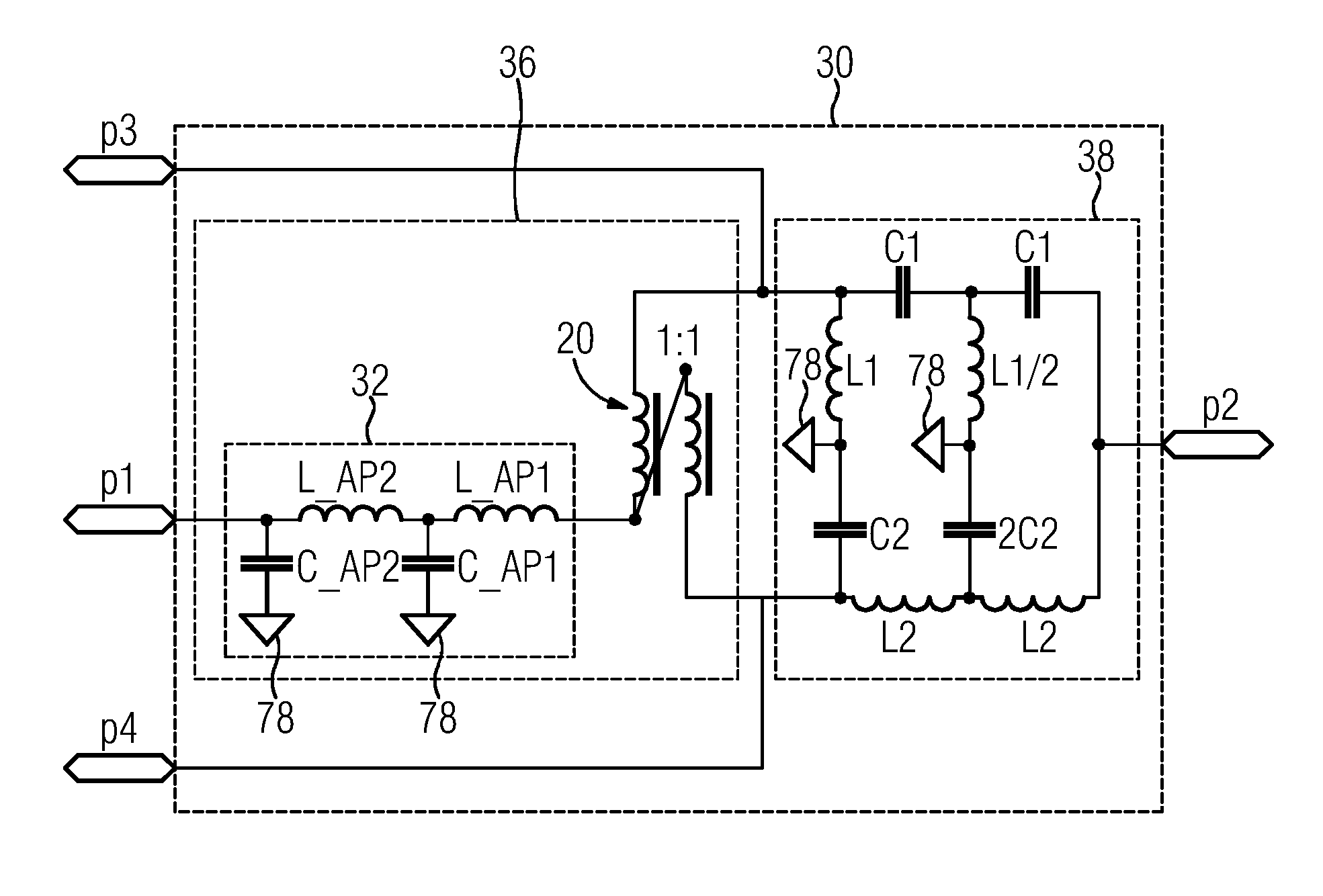
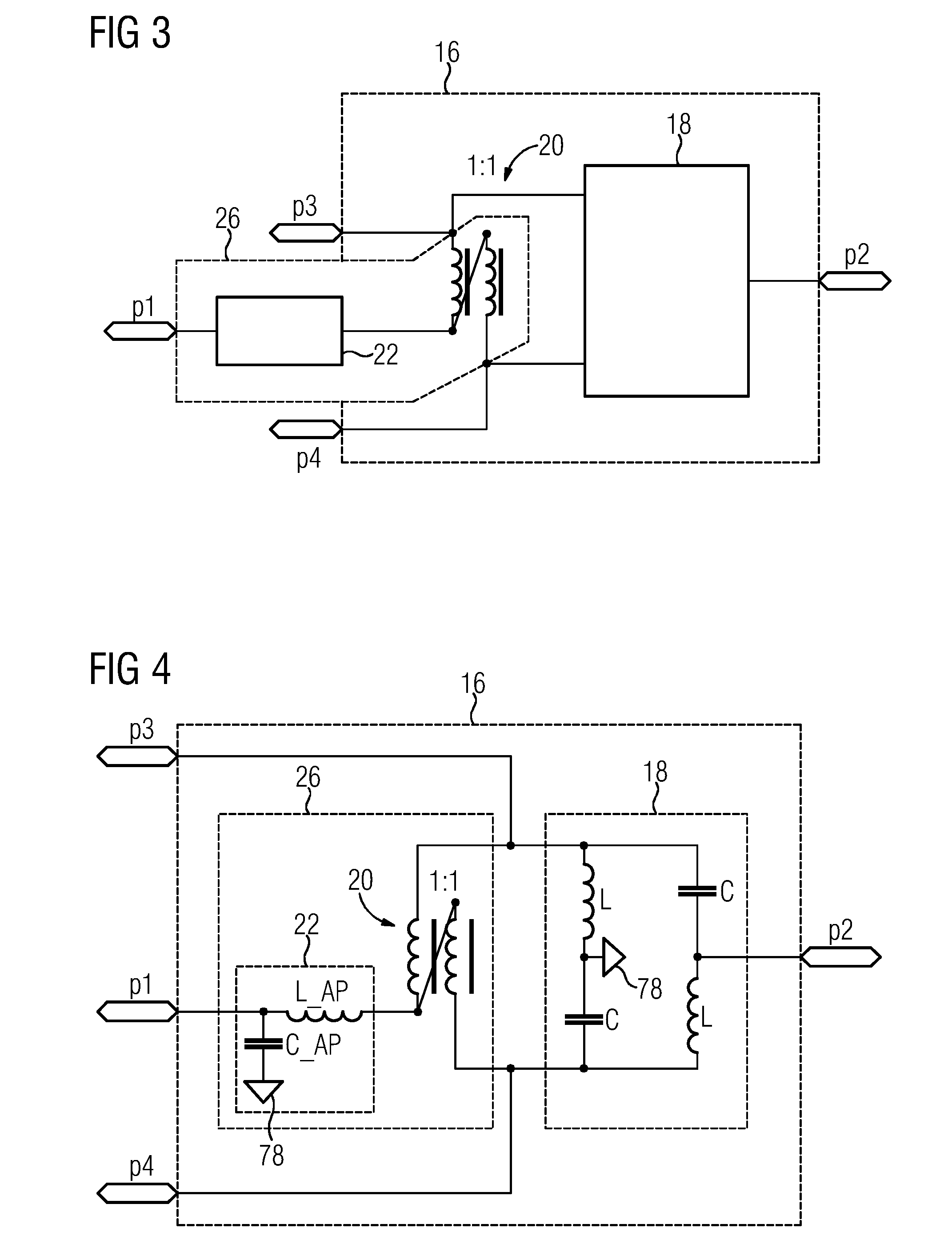
[0012]This configuration makes it possible to avoid the complex transformer having three windings, in contrast to a directional coupler of the generic type. Owing to the use of the second coupling network, the transformer winding required in the case of the directional coupler according to the generic type for providing the connection for the second port may be dispensed with. At the same time, the second coupling network makes it possible to adjust the characteristic impedance to the desired value, in particular so as to match it to the characteristic impedances of the two other ports to which the coupling network is connected. As a result, the procurement and design of the directional coupler may be improved. The complex transformer having three windings may be avoided. Furthermore, a directional coupler that requires fewer components and may be used with a wider bandwidth, in comparison with the ring coupler or the rat race coupler, may be provided. Finally, the characteristic impedance of the four ports of the directional coupler may be substantially identical.
[0013]Furthermore, in certain embodiments, a magnetic resonance tomography device is provided, the device including electrical transmission coils arranged in a housing providing a ring-shaped space and a radiofrequency generator applying radiofrequency electric power to the electrical transmission coils and including reception coils. The magnetic resonance tomography device also includes a directional coupler. It is thus possible to configure the magnetic resonance tomography device overall to be more cost-effective and compact. Owing to the use of the advantages of the directional coupler, the magnetic resonance tomography device may thus be improved overall. The ring-shaped space may be round and / or angular along its ring-shaped extent. Furthermore, the ring-shaped space may have, for example, a substantially angular, in particular rectangular or else round cross section, such as, for example, a torus or the like. The transmission coils may be arranged in the ring-shaped space of the housing. The reception coils may likewise be arranged in the ring-shaped housing. However, the reception coils may alternatively also be arranged outside the ring-shaped housing, for example, adjacent to the housing or else on a patient who is positioned within a through-opening provided through the housing.
[0017]In accordance with a further configuration, the first and second coupling networks are connected in parallel to the connections for the third and fourth ports. This configuration makes it possible to further reduce the number of component parts by virtue of, for example, selected functions being realized by the parallel circuit by common component parts.
[0021]Furthermore, the embodiments propose that the first coupling network has two capacitances, which are connected between the reference potential and in each case one of the third and fourth ports, two inductances, which are connected between the first port and in each case one of the third and fourth ports, and a capacitance, which is connected between the first port and the reference potential. This configuration has proved favorable, in particular, in the parallel circuit with the second coupling network since savings may additionally be made in respect of components in this case, (e.g., when the first and second coupling networks are connected in parallel). Furthermore, it is possible with this configuration to completely avoid the transformer. This reduces costs and complexity for the directional coupler.
[0023]It has proven to be particularly advantageous if the directional coupler is in the form of a 180° hybrid. As a result, it may be produced reproducibly in a simple manner and with a low level of installation complexity being involved. In one example, the 180° hybrid consists exclusively of line sections that are connected to one another dually as discrete components.

Problems solved by technology

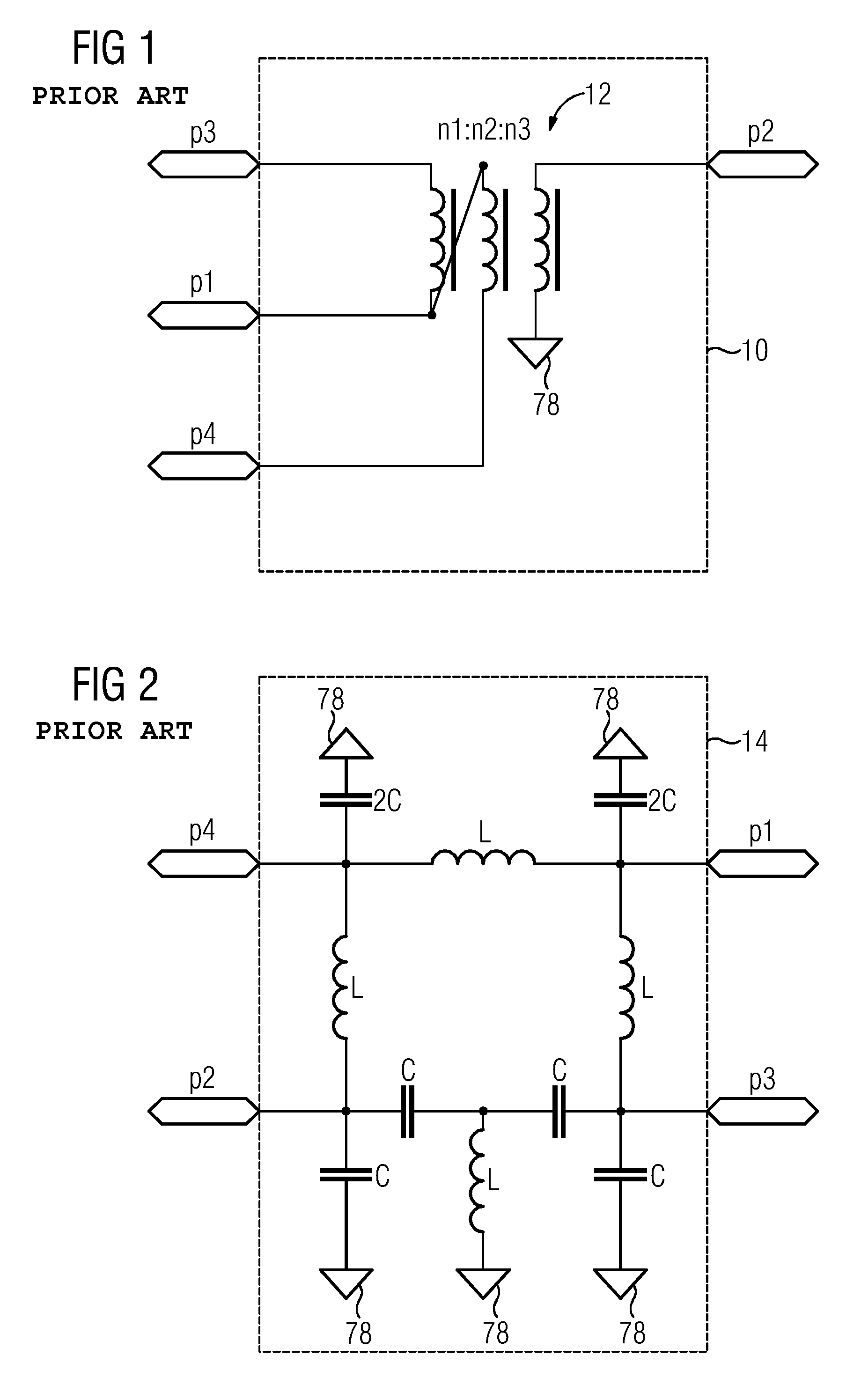
Directional couplers are made to specification in small numbers, in particular, in the high-power range, and are therefore correspondingly complex to manufacture.
The directional couplers require a large amount of installation space for high powers and are therefore expensive.
The use of the transformer has the disadvantage that, in this case, not always the same characteristic impedance is available at the ports of the directional coupler.
Although the characteristic impedance may be matched by matching of the transformation ratio of the windings with respect to one another, such a winding may not be wound in trifilar fashion, which results in further problems, in particular, in respect of the coupling factor.
Furthermore, a problem with respect to the value of the characteristic impedance remains at one or more of the ports.
However, the problem of non-uniform characteristic impedances at the four ports remains in this case too.

Method used


Image

  • Directional Coupler
  • Directional Coupler
  • Directional Coupler

Examples


Embodiment Construction

[0040]If, for example, in the case of a 180° hybrid, a radiofrequency signal is fed into any one of its ports, the power of this radiofrequency signal is distributed among two output ports, (e.g., with approximately the same magnitude). There may be substantially no power available at the third port, for which reason the third port is also referred to as decoupled port in this case. In the case of a 180° hybrid, the phase difference between the signals at the output ports at which half the power is provided is either 0° or 180°. Besides this, there are also 90° hybrids in which the corresponding phase difference is then 0° or 90°.

[0041]The signal behavior of a hybrid, in particular of a 180° hybrid, may be characterized by the scattering matrix specified below, occasionally also referred to as S-matrix. In contrast to an ideal scattering matrix in which the phases between input and output ports are also strictly defined, in practice often only the phase difference between the two po...


PUM

PropertyMeasurementUnit
relative phase angleaaaaaaaaaa
frequenciesaaaaaaaaaa

Abstract

The embodiments relate to a directional coupler including, in each case, one connection for a first, a second, a third, and a fourth port. The coupler includes a first coupling network for providing the connection for the first port and a second coupling network for providing the connection for the second port. The first and second coupling networks are both connected to the connections for the third and fourth ports, wherein the second coupling network has a first inductance connected between the third port and an electrical reference potential, a first capacitance connected between the fourth port and the electrical reference potential, a second capacitance connected between the third port and the second port, and a second inductance connected between the fourth port and the second port.

Description

CROSS-REFERENCE TO RELATED APPLICATIONS[0001]This application claims the benefit of DE 10 2014 203 228.8, filed on Feb. 24, 2014, which is hereby incorporated by reference in its entirety.TECHNICAL FIELD[0002]The present embodiments relate to a directional coupler having in each case one connection for a first, a second, a third, and a fourth port. Furthermore, the embodiments also relate to a magnetic resonance tomography device including electrical transmission coils arranged in a housing providing a ring-shaped space and a radiofrequency generator, which applies radiofrequency electric power to the electrical transmission coils, and also includes reception coils.BACKGROUND[0003]A directional coupler is in principle a reciprocal, loss-free four-port structure, in which each port is decoupled from one of the three other ports. Directional couplers, and the design and use of said directional couplers are described, inter alia, in “Taschenbuch der Hochfrequenztechnik” [“Pocketbook of...

Claims


Application Information

Patent Timeline
Patent Type & Authority Applications(United States)
IPC IPC(8): H01P5/18G01R33/36H03H7/38G01R33/34H01F30/02H01F38/14
CPCH01P5/18H01F30/02H01F38/14H01F2038/146G01R33/34092G01R33/36H03H7/38H03H7/48H01F38/023H01F2038/026
Inventor OPPELT, RALPH
Owner SIEMENS HEALTHCARE GMBH
Why Eureka
Try Eureka