Supercharge Your Innovation With Domain-Expert AI Agents!

Image Processing in a Multi-Channel Camera

Active Publication Date: 2015-05-07
APPLE INC
View PDF9 Cites 12 Cited by
  • Summary
  • Abstract
  • Description
  • Claims
  • Application Information

AI Technical Summary

Benefits of technology

This patent is about a camera system with multiple imaging channels that capture images from different perspectives. The system uses color filters to measure object distance and calculate the position of objects in the scene. The technical effect of this patent is to improve the accuracy and reliability of image processing in a camera system with multiple imaging channels. By measuring object misalignment and applying shifts to misaligned objects, the system can accurately determine the distance of objects in a scene and create a combined luminance signal with higher dynamic range. The patent also describes the use of a white color filter to capture preliminary images with better signal-to-noise ratios and low light performance.

Problems solved by technology

One challenge introduced with the use of three or more imaging channels, each including a different color filter is the possibility that a particular image feature may not appear in more than one preliminary image in view of the different spectra associated with each imaging channel.

Method used


Image

  • Image Processing in a Multi-Channel Camera
  • Image Processing in a Multi-Channel Camera
  • Image Processing in a Multi-Channel Camera

Examples


example camera

System

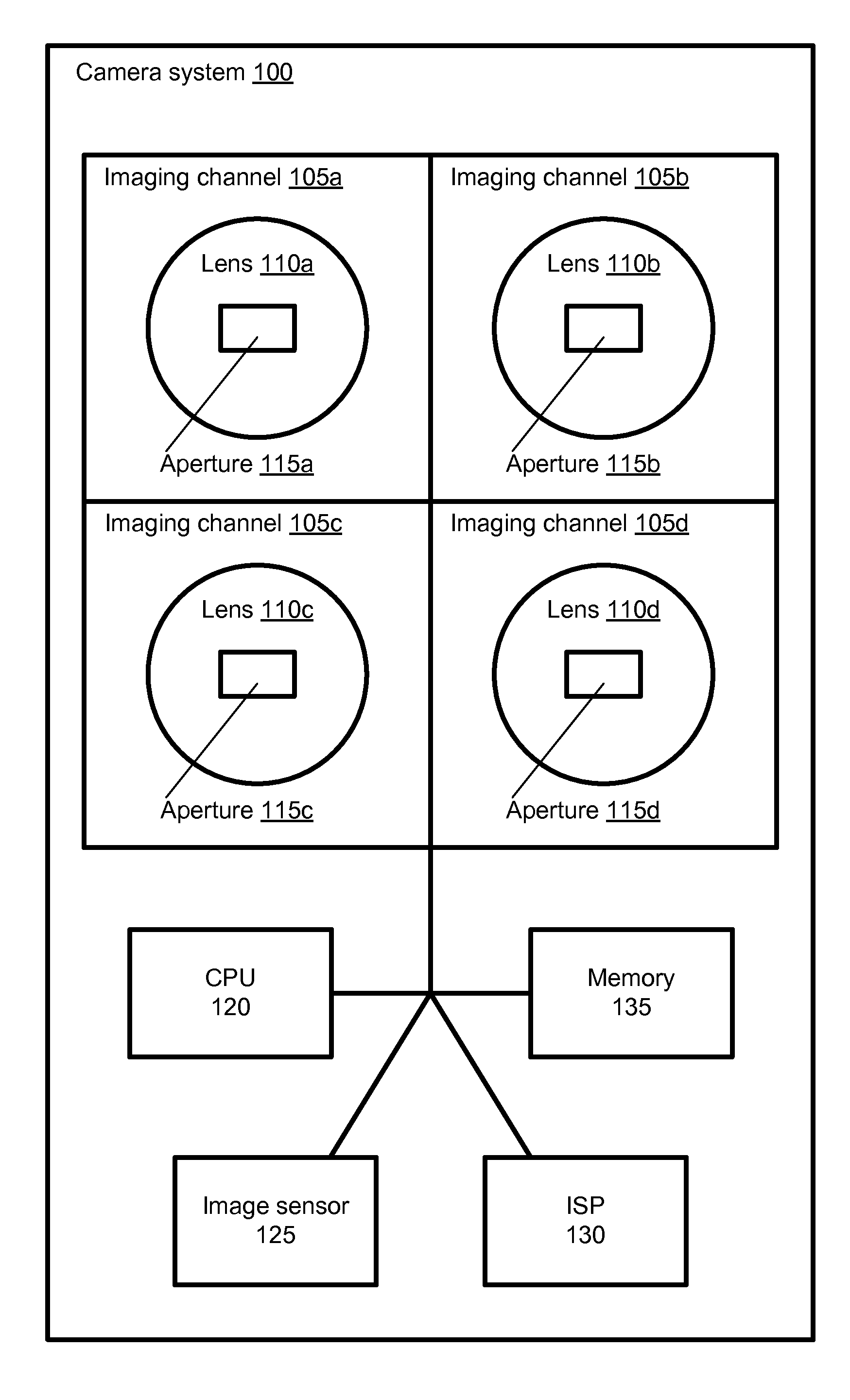
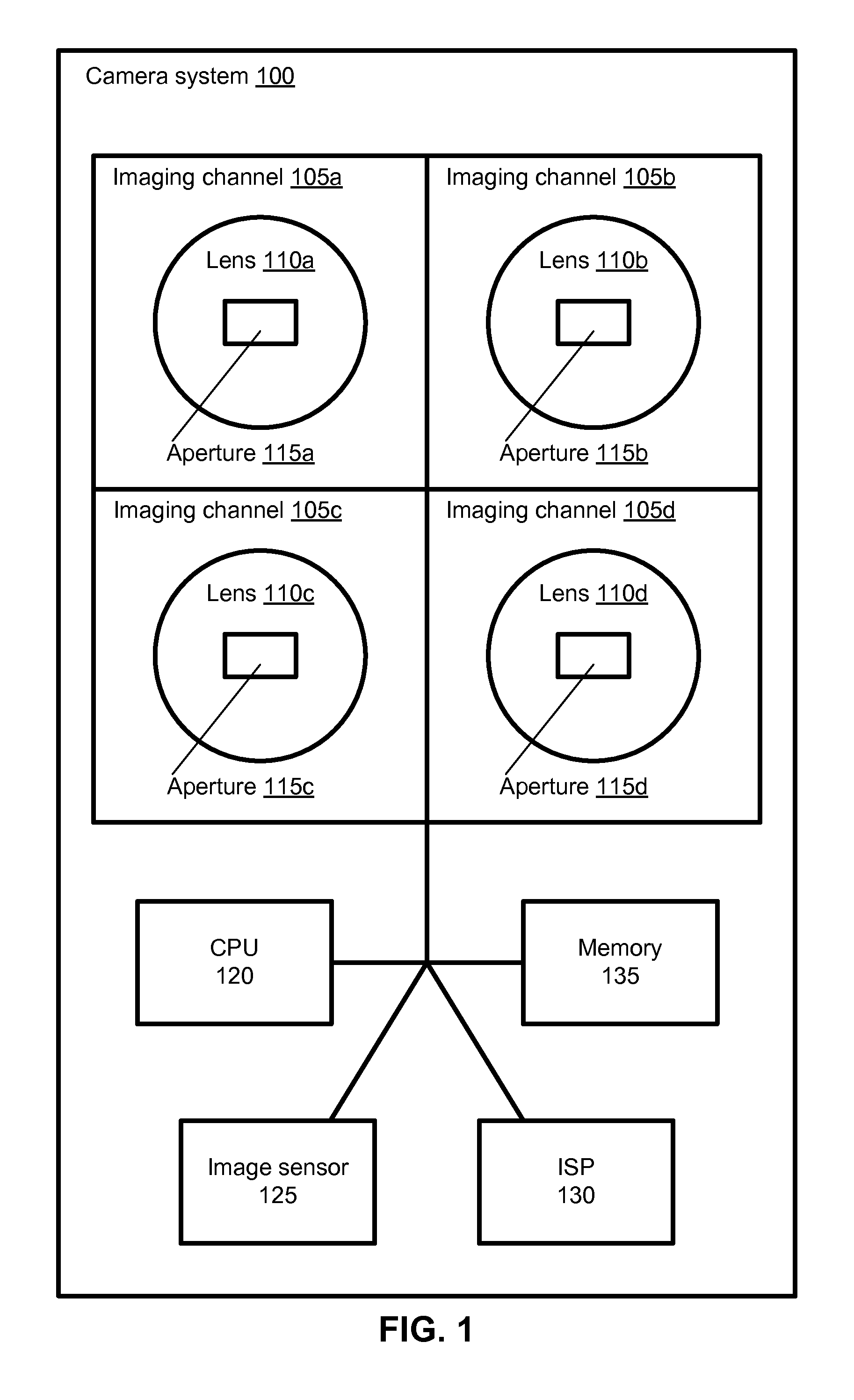
[0020]FIG. 1 illustrates a camera system with multiple imaging channels, according to one example embodiment. The camera system 100 in the embodiment of FIG. 1 includes four imaging channels, imaging channels 105a, 105b, 105c, and 105d (collectively “imaging channels 105”). Each imaging channel 105a-d includes a lens 110a-d (“lenses 110”) and an aperture 115a-d (“apertures 115”), respectively. It should be noted while the embodiment of FIG. 1 illustrates four imaging channels to a 2×2 array, in other embodiments can include any number of imaging channels in any arrangement. In addition, each of the imaging channels illustrated in FIG. 1 can include one or more chromatic filters (not shown in FIG. 1).

[0021]The camera system 100 also includes a central processing unit (“CPU”) 120, an image sensor 125, an image signal processor (“ISP”) 130, and a memory 135. Other embodiments of the camera system 100 can include fewer, additional, or different components, and the functionalities ...


PUM


Abstract

An imaging system is configured to identify an object represented by a plurality of preliminary images. The preliminary images are each associated with a different camera imaging channel, and include different image information. An object distance is determined based on the difference in preliminary image information. An object shift is determined based on the object distance and a pre-determined relationship between object shift and object distance. The object shift is applied to the portions of one or more preliminary images representing the object to form shifted preliminary images, and the shifted preliminary images are combined to form a final image.

Description

CROSS REFERENCE TO RELATED APPLICATIONS[0001]This application claims priority to U.S. Provisional Application No. 61 / 667,960, filed on Jul. 4, 2012, the contents of which are hereby incorporated by reference in their entirety.BACKGROUND[0002]1. Technical Field[0003]This disclosure relates to image processing, and more specifically, to image processing in a camera system with multiple imaging channels.[0004]2. Description of Related Art[0005]Cameras with multiple imaging channels enable the extraction of distance information for objects in a captured image. For example, a captured image of a scene including a dog, a tree, and a cloud can be analyzed to determine a first distance from the camera to the dog, a second distance from the camera to the tree, and a third distance from the camera to the cloud. The distance between lenses in such cameras can create a parallax effect causing objects to appear at different positions within the images captured by each imaging channel. Calculatin...

Claims


Application Information

Patent Timeline
IPC IPC(8): G06T7/20H04N5/247H04N9/097
CPCG06T7/2093H04N9/097G06T2207/30241G06T2207/10004G06T2207/10024H04N5/247G06T3/4038G06T7/30G06T7/292H04N23/16H04N23/90
Inventor ATTAR, ZIVTOVCHIGRECHKO, ANDREY
Owner APPLE INC
Features
  • R&D
  • Intellectual Property
  • Life Sciences
  • Materials
  • Tech Scout
  • Unparalleled Data Quality
  • Higher Quality Content
  • 60% Fewer Hallucinations
Learn More