Image Reconstruction Methods Based on Block Circulant System Matrices

a circulant system and image reconstruction technology, applied in tomography, nuclear engineering, instruments, etc., can solve the problems of high condition number (cn), false detection, and presence of artefacts in the reconstructed image, and achieve the effect of reducing the size of the system matrix

Inactive Publication Date: 2009-05-14
SOCPRA SCI SANTE & HUMAINES S E C
View PDF5 Cites 92 Cited by
  • Summary
  • Abstract
  • Description
  • Claims
  • Application Information

AI Technical Summary

Benefits of technology

[0030]An object of the present invention is to provide an imaging system and method to model the response functions of the apparatus which minimize the size of the system matrix that can be used by direct and / or by iterative image reconstruction methods.
[0031]Another object of the present invention is to provide fast methods for computing the pseudo-inverse of the said probability matrix using singular value decomposition and fast methods to compute the image using the pseudo-inverse matrix.

Problems solved by technology

Some drawbacks of the method is the presence of artefacts and the misplacements of some radioactive objects in the reconstructed image due to the over-simplification of the TOR functions by an infinite thin line.
In that respect, characteristics like spatial resolution, image contrast, signal-to-noise (S / N) ratio are aspects which can improve the detection accuracy but these should not be obtained at the expense of having some artefacts in the image which could lead to false detections.
One of the drawback of the method is the high condition number (CN) (largest divided by smallest eigenvalue) of the blurring matrix for tomographic reconstruction problems.
Another drawback is the computational burden of the pseudo-inversion operation.
However, Vandenberghe fails to include the modeling of the system in the backprojection matrix.
A drawback of performing the SVD directly on the probability matrix A is the computational burden of decomposing such a large matrix for ill-posed problems.
However, due to limitations in computation power, available memory size and floating point precision of current computer, the SVD inversion can only be performed for modest size imaging problem.
Nevertheless, a drawback of iterative methods is the computational burden coming from the many iterations required before the image reach final convergence.
Nevertheless, this oversimplification of the initial problems can lead to mispositioning and / or to non-optimal estimate of some source activity in the 3D image.
For most iterative image reconstruction algorithms the main computational burden comes from the matrix-vector operations involved in the forward and back projection steps that are performed at each iteration loop.
However, for some complex 3D image reconstruction problems, the sparse probability matrix could still be very huge.
The size of the probability matrix is really becoming a problem when it is too large to fit in the random access memory (RAM) of a given processor or dedicated hardware computational unit.
The overhead of reading large amount of information on a hard disk could lead to very long delay for the image reconstruction procedure.
Those simplifications in the system matrix will affect the quality of the reconstructed image.
One drawback of the polar image configuration used by Kearfott is that a fixed number of pixels are used at every radius position which has the consequence of dividing the image into very thin pixels at the center and into wide pixels at the border of the field of view.
The important size disparities between the innermost and the outermost pixels of the image could result in over resolution in the center of the image and in degradation of the imaging system spatial resolution farther from the center.
However, the proposed polar image reconstruction algorithm did not result in significant acceleration of the forward and back projection steps.
One drawback of converting the probability matrix in the Fourier domain comes from the fact that a lot of null values in the matrix become non-null during the Fourier transform which increase the matrix size.
Another drawback of the method proposed by Hebert, is that the polar image used has a constant number of pixels at every radius position which results in size disparities between innermost and outermost pixels.
However, this conversion from a polar to a Cartesian image representation and then from a Cartesian to a polar image representation can result in a loss of spatial resolution due to divergences between the pixels size and position of the polar and Cartesian images.
Moreover, since a dense system matrix in the Fourier domain is used in the computation, the gain of speed compared to the traditional method based on a sparse system matrix in the spatial domain rapidly vanishes as the number of symmetries in the camera become small compared to the number of detectors within a ring.

Method used


Image

  • Image Reconstruction Methods Based on Block Circulant System Matrices
  • Image Reconstruction Methods Based on Block Circulant System Matrices
  • Image Reconstruction Methods Based on Block Circulant System Matrices

Examples


Embodiment Construction

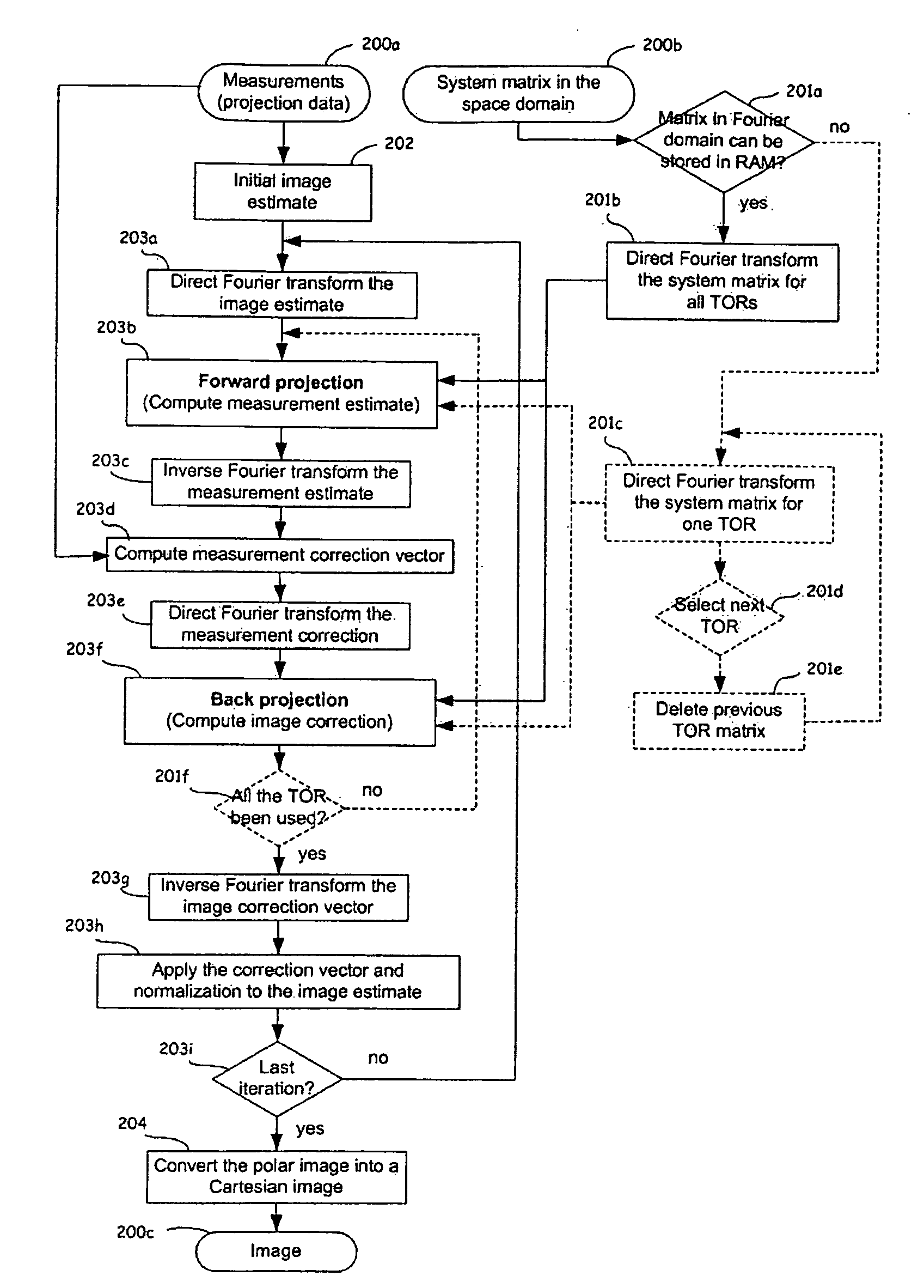
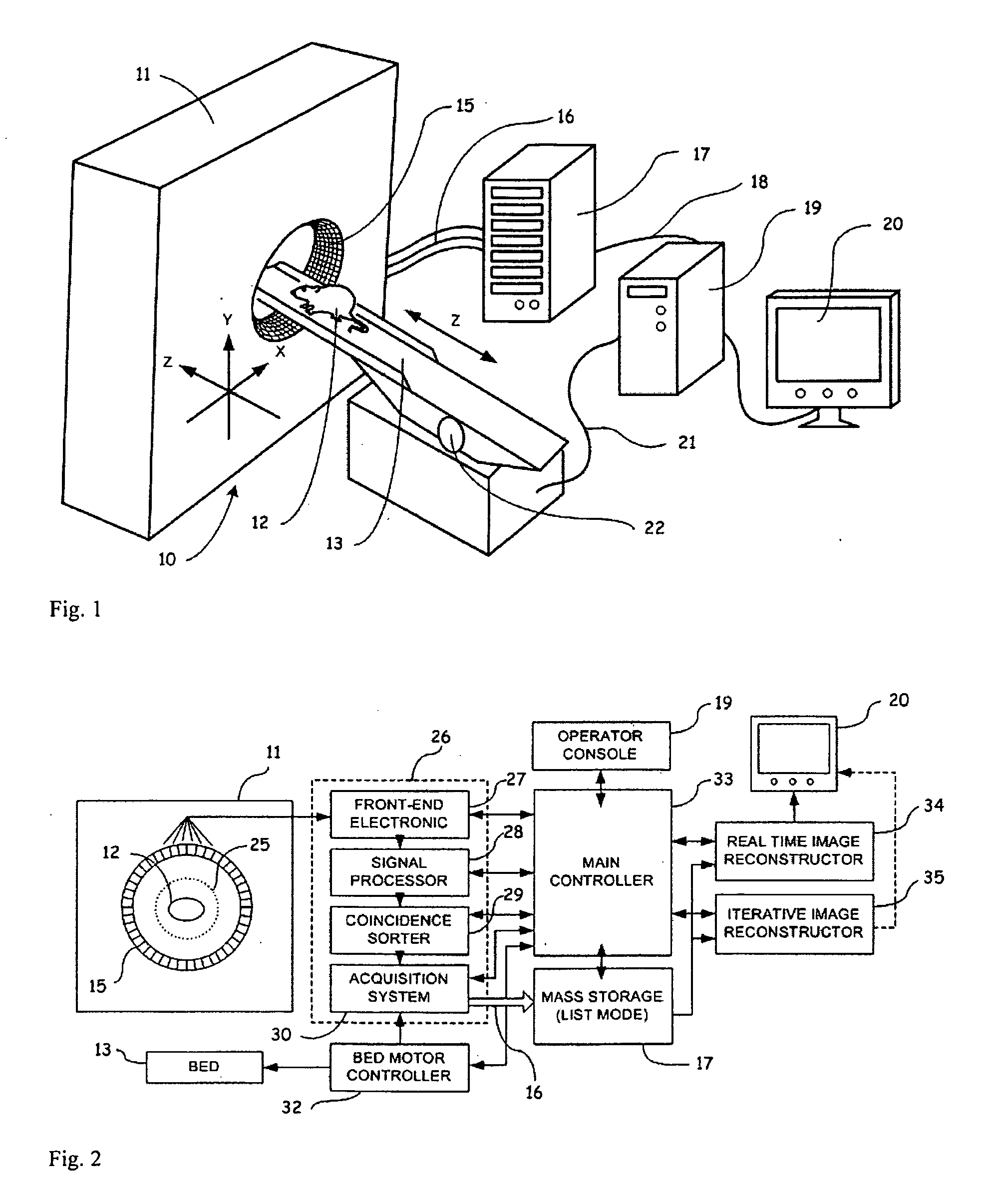
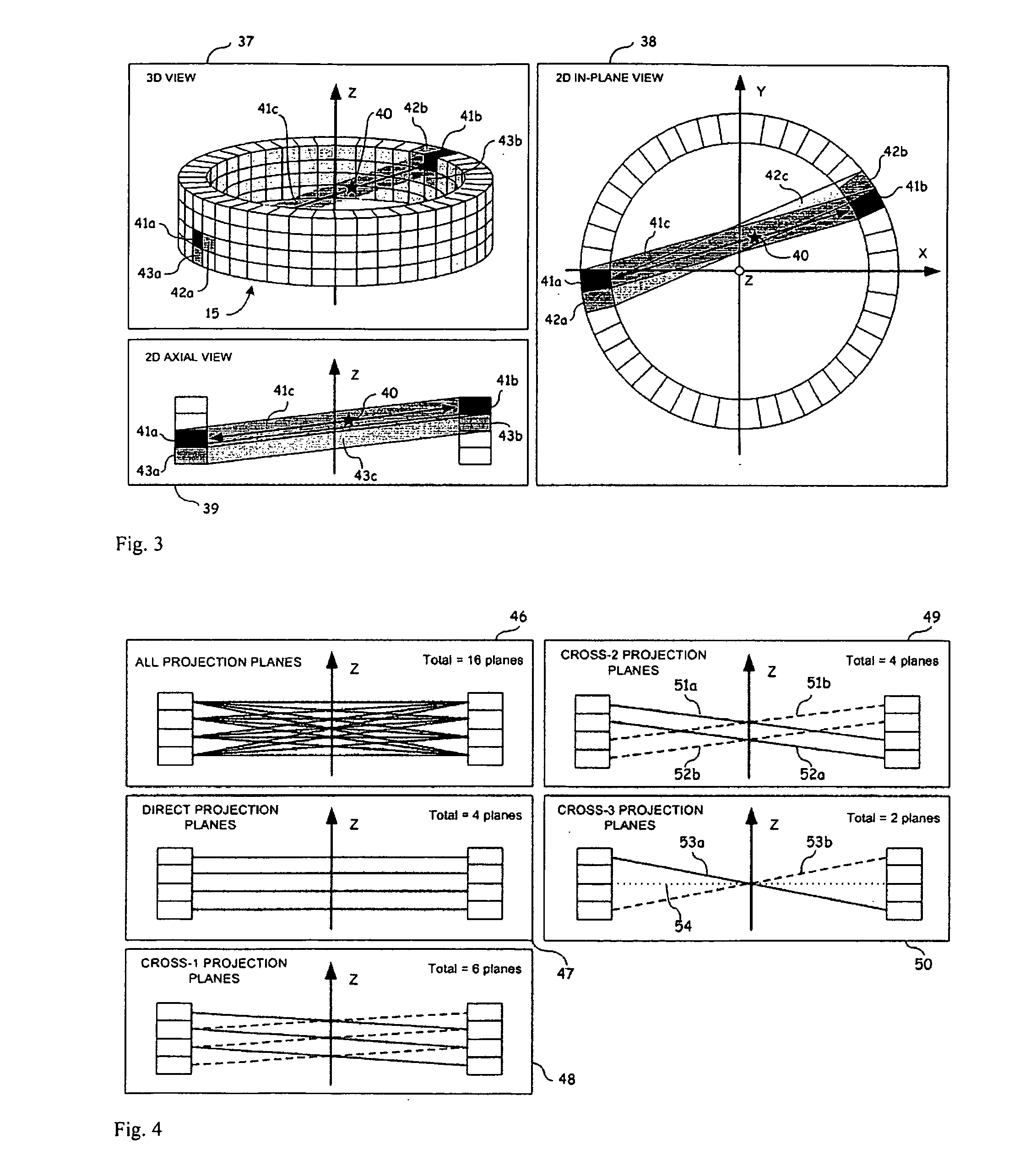
[0063]Generally stated, a non-restrictive illustrative embodiment of the present invention provides for an imaging system and methods of computing image reconstructions using a system matrix that relates the measurements of the imaging system to the pixels (or voxels) of the image, wherein the pixels (or voxels) are positioned according to a polar or cylindrical coordinate grid. The imaging system can be measuring Positron Emission Tomography (PET) or can be other imaging modalities, for example, but not restricted to, Computed Tomography (CT), Single Photon Emission Computed Tomography (SPECT) and ultrasound imaging (US). The polar or cylindrical image is discretized according to basis functions defined over a polar coordinates image grid in such a way that the symmetries present between the tubes of responses (TORs) of the imaging system are preserved during the computation of the system matrix coefficients. Those symmetries allow to reorder the system matrix into a block circulan...


PUM


Abstract

An iterative image reconstruction method used with an imaging system that generates projection data, the method comprises: collecting the projection data; choosing a polar or cylindrical image definition comprising a polar or cylindrical grid representation and a number of basis functions positioned according to the polar or cylindrical grid so that the number of basis functions at different radius positions of the polar or cylindrical image grid is a factor of a number of in-plane symmetries between lines of response along which the projection data are measured by the imaging system; obtaining a system probability matrix that relates each of the projection data to each basis function of the polar or cylindrical image definition; restructuring the system probability matrix into a block circulant matrix and converting the system probability matrix in the Fourier domain; storing the projection data into a measurement data vector; providing an initial polar or cylindrical image estimate; for each iteration; recalculating the polar or cylindrical image estimate according to an iterative solver based on forward and back projection operations with the system probability matrix in the Fourier domain; and converting the polar or cylindrical image estimate into a Cartesian image representation to thereby obtain a reconstructed image.

Description

PRIORITY CLAIM[0001]This application claims the benefit of U.S. Provisional Patent Application Ser. No. 60 / 924,311 filed on May 9, 2007, the specification of which is expressly incorporated herein, in its entirety, by reference.FIELD OF THE INVENTION[0002]The present invention relates to the reconstruction of images, in particular but not exclusively tomographic images representing the distribution of some characteristic across a sectional plane (2D mode) or a volume (3D mode) of a body under investigation, from measurements of an apparatus.[0003]The present invention relates more particularly, but not exclusively, to iterative reconstruction methods and to direct reconstruction methods based on the singular value decomposition (SVD) used for Positron Emission Tomography (PET) and for Single Photon Emission Computed Tomography (SPECT) and for Computed Tomography (CT).BACKGROUND[0004]Tomography refers to the cross-sectional imaging of an object from either transmission, emission or r...

Claims


Application Information

Patent Timeline
Patent Type & Authority Applications(United States)
IPC IPC(8): G06K9/00H05G1/60G01T1/166A61B6/00
CPCG06T11/006A61B6/037A61B6/508G06T2211/424
Inventor LEROUX, JEAN-DANIELFONTAINE, REJEANLECOMTE, ROGERSELIVANOV, VITALI
Owner SOCPRA SCI SANTE & HUMAINES S E C
Why Eureka
Try Eureka