Near infrared guided image denoising

a technology of infrared guided image and denoising, which is applied in the field of imaging systems and methods, can solve the problems of inability to take high-quality photographs and videos under low light conditions, inability to improve the signal-to-noise ratio (snr) and inability to take high-quality photographs and videos

Active Publication Date: 2015-05-07
QUALCOMM INC
View PDF1 Cites 37 Cited by
  • Summary
  • Abstract
  • Description
  • Claims
  • Application Information

AI Technical Summary

Problems solved by technology

It can be challenging to take high quality photographs and videos under low light conditions.
However, the image noise is inevitably increased as well, thus the signal-to-noise ratio (SNR) is not improved.
Further, the effect is very limited when sensor and lens have been built to accommodate a small form factor, e.g. cell phone cameras.
Extended exposure time can increase SNR, but may increase undesired motion blur in the captured image.
However, as the color temperature and intensity of flash light are usually quite different from those of the ambient light, the use of flash may ruin ambiance atmosphere and introduce unwanted artifacts, such as red eye, undesired reflections, harsh shadows, and intense light highlights and reflections.
However, even with the state-of-the-art image de-noising methods, it is still very difficult to obtain a high quality noise-free photo, especially when noise level is high.
However, a common fundamental problem with single-image de-noising approaches is that they are not able to distinguish between noise and original image signals, especially with respect to the finer image details.
Hence, those approaches generate reasonably good-quality results for images with relatively low noise levels, but generally produce over-smoothened results with many artifacts for images containing high noise levels.
However, this method can easily blur weak edges and introduce artifacts from the guidance image.
However, the gradient constraint from the dark flash image may be too heuristic and not well adapted to handle the differences between the visible light image and the dark flash image.
This results in a noticeable appearance change in the de-noising results, especially when handling images with intensive noise.

Method used


Image

  • Near infrared guided image denoising
  • Near infrared guided image denoising
  • Near infrared guided image denoising

Examples


Embodiment Construction

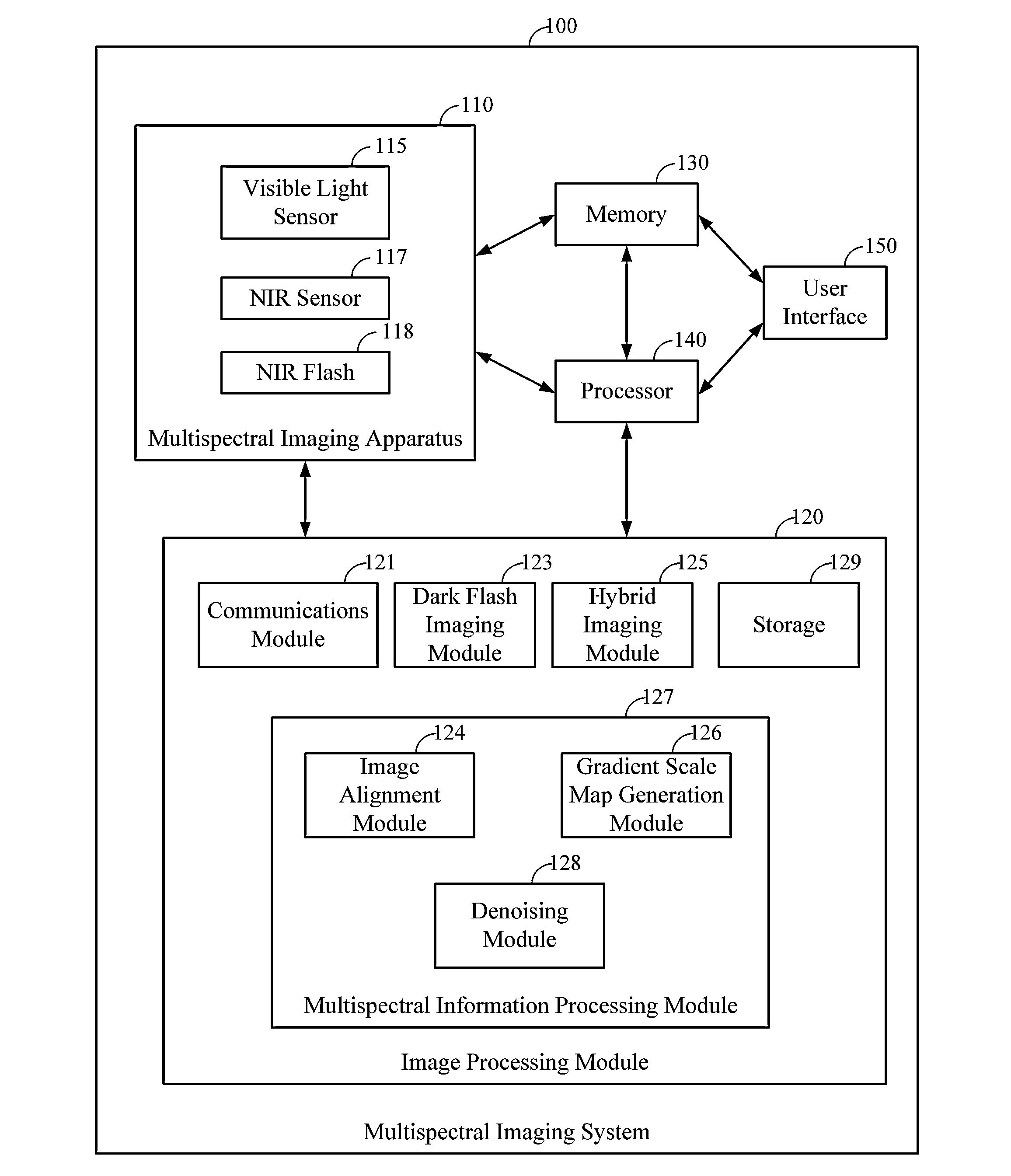
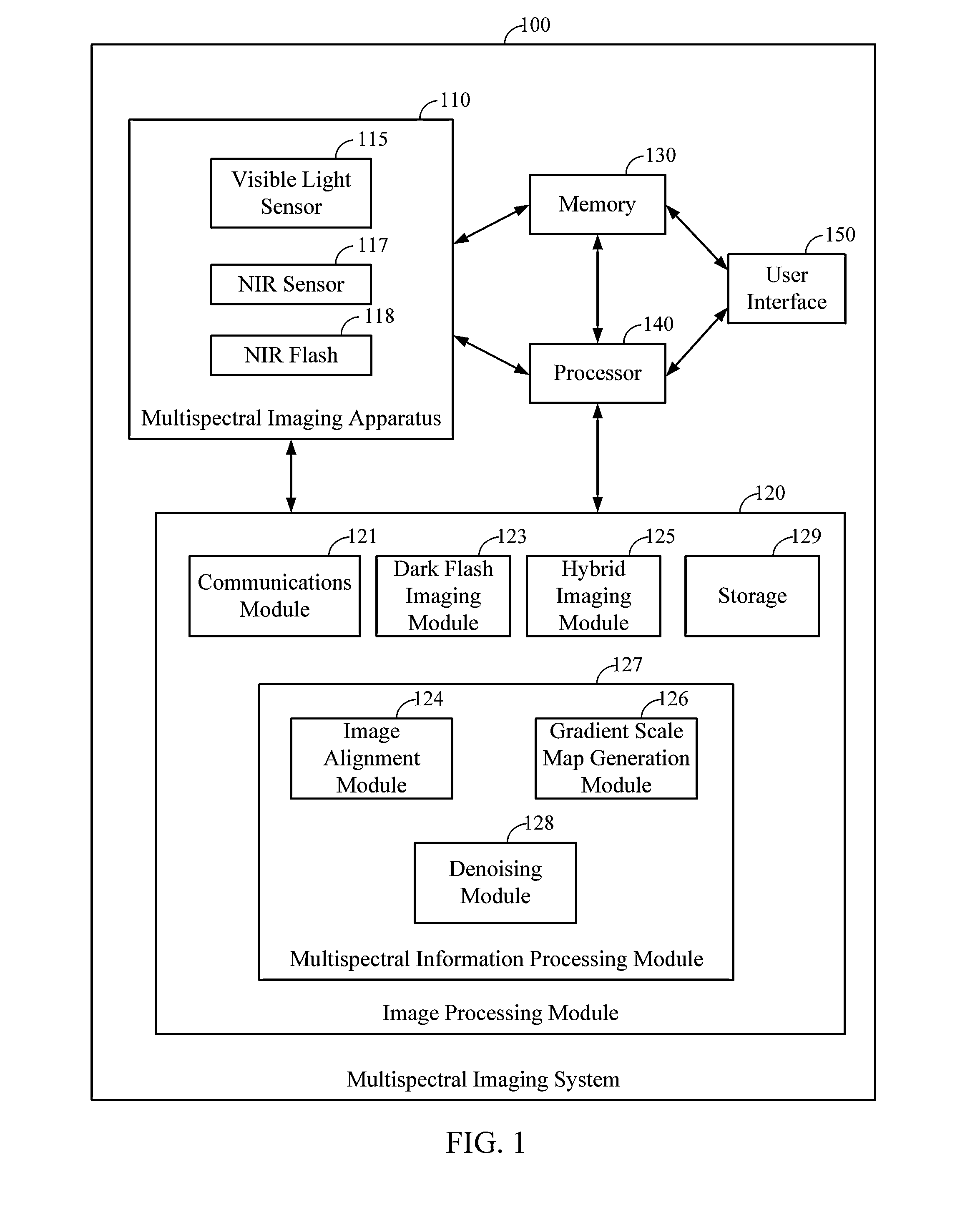
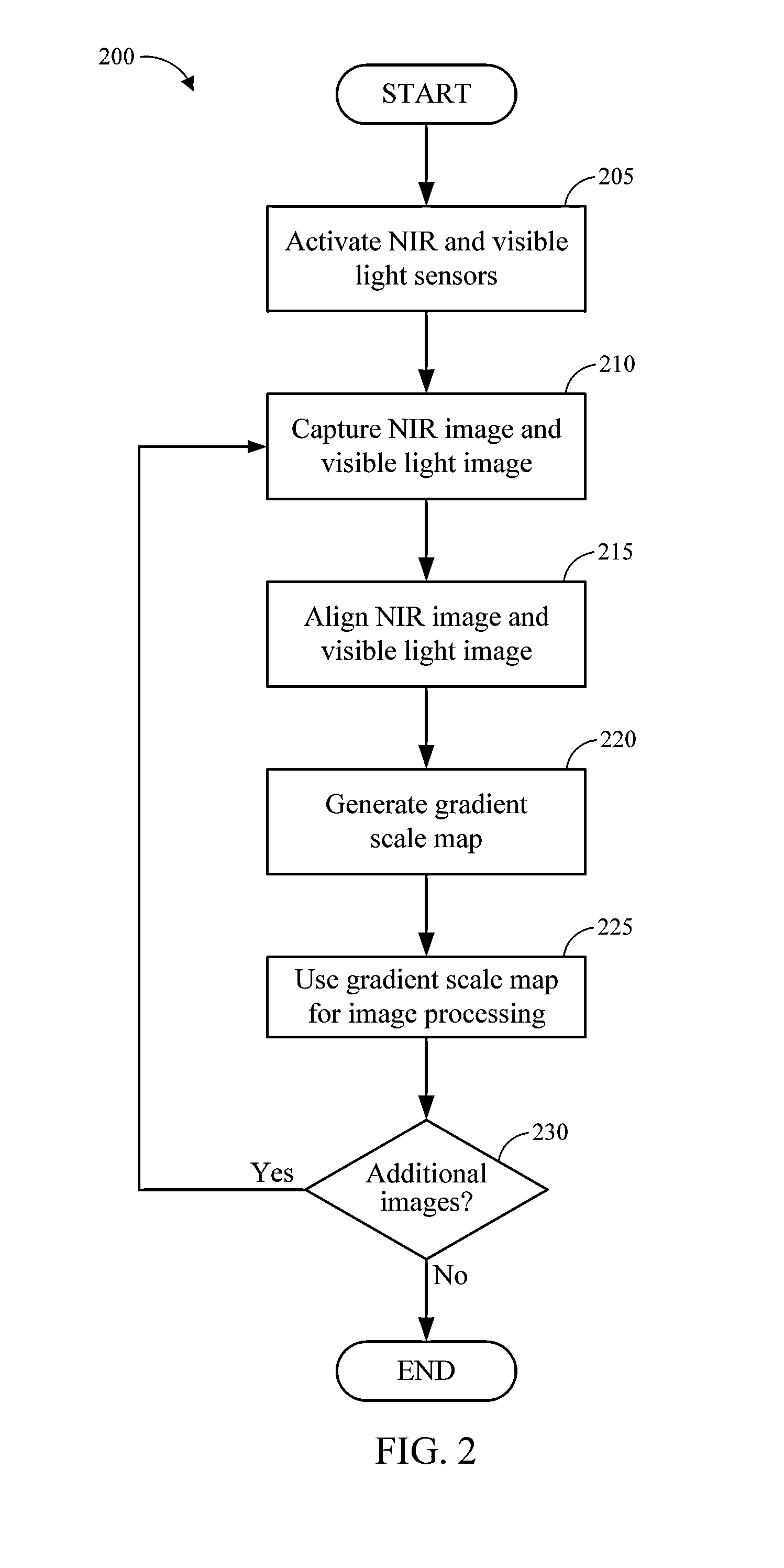
[0020]Implementations disclosed herein provide systems, methods and apparatus for image de-noising applications. For example, as explained herein, it can be desirable to process a high-quality image from a noisy visible light image using a corresponding dark flash image, such as a near infrared (NIR) image. Although embodiments are described herein as employing NIR images, it will be appreciated that infrared and ultraviolet flash images may be used as well. The implementations disclosed herein can be used to capture a pair of visible light, for example RGB, and NIR images of the same image scene. During a de-noising process, the visible light and NIR images may be aligned on a pixel bases, and a gradient scale map may be introduced to relate gradient fields of the aligned visible light and NIR images.

[0021]The gradient scale map may be generated based on the differences and similarities between the gradient vectors of the visible light image and the gradient vectors of the NIR imag...


PUM


Abstract

Systems and methods for multispectral imaging are disclosed. The multispectral imaging system can include a near infrared (NIR) imaging sensor and a visible imaging sensor. The disclosed systems and methods can be implemented to de-noise a visible light image using a gradient scale map generated from gradient vectors in the visible light image and a NIR image. The gradient scale map may be used to determine the amount of de-noising guidance applied from the NIR image to the visible light image on a pixel-by-pixel basis.

Description

CROSS-REFERENCE TO RELATED APPLICATIONS[0001]The present application claims the benefit under 35 U.S.C. §119(e) of U.S. Provisional Patent Application No. 61 / 811,610, filed on Apr. 12, 2013, entitled “NEAR INFRARED GUIDED IMAGE DENOISING,” the entire contents of which is hereby incorporated by reference herein in its entirety and for all purposes.BACKGROUND OF THE INVENTION[0002]1. Field of the Invention[0003]The present disclosure relates to imaging systems and methods that include a de-noising process. In particular, the disclosure relates to systems and methods that use a near infrared image to guide the de-noising process.[0004]2. Description of the Related Art[0005]It can be challenging to take high quality photographs and videos under low light conditions. Without sufficient ambient light, photographers generally have four options to increase picture quality. The first option is to use a high ISO when capturing the image. Increasing sensor gain can effectively increase signal ...

Claims


Application Information

Patent Timeline
Patent Type & Authority Applications(United States)
IPC IPC(8): G06T5/00G06T7/00
CPCG06T7/004G06T5/002G06T5/50G06T2200/21G06T2207/10016G06T2207/10024G06T2207/10048G06T2207/20012G06T2207/20192G06T7/70
Inventor ZHUO, SHAOJIEZHANG, XIAOPENGFENG, CHENSHEN, LIANGJIA, JIAYA
Owner QUALCOMM INC
Why Eureka
Try Eureka