
Helical DeNervation Ablation Catheter Apparatus

a denervation ablation and catheter technology, applied in the field of catheter equipment, can solve the problems of resistance hypertension and failure to achieve a targeted level of blood pressure, high rates of cardiovascular disease and death, etc., and achieve the effect of low level of rf energy

Inactive Publication Date: 2015-05-07
MOGUL ENTERPRISES
View PDF7 Cites 24 Cited by
  • Summary
  • Abstract
  • Description
  • Claims
  • Application Information

AI Technical Summary

Benefits of technology

The technical problem addressed in this patent text is how to use radiofrequency energy to denervate the renal sympathetic nerves without affecting other nerves in the abdomen and lower-extremity.

Problems solved by technology

Hypertension is associated with high rates of cardiovascular disease and death.
However, various studies indicate that the control rate remains suboptimal or the blood pressure is non-respondent or resistant to the drug treatment for a subset of population.
Resistant hypertension is a failure to achieve a targeted level of blood pressure in patients who adhere to full tolerated doses of an appropriate three-drug regimen.

Method used


Image

  • Helical DeNervation Ablation Catheter Apparatus
  • Helical DeNervation Ablation Catheter Apparatus
  • Helical DeNervation Ablation Catheter Apparatus

Examples


first embodiment

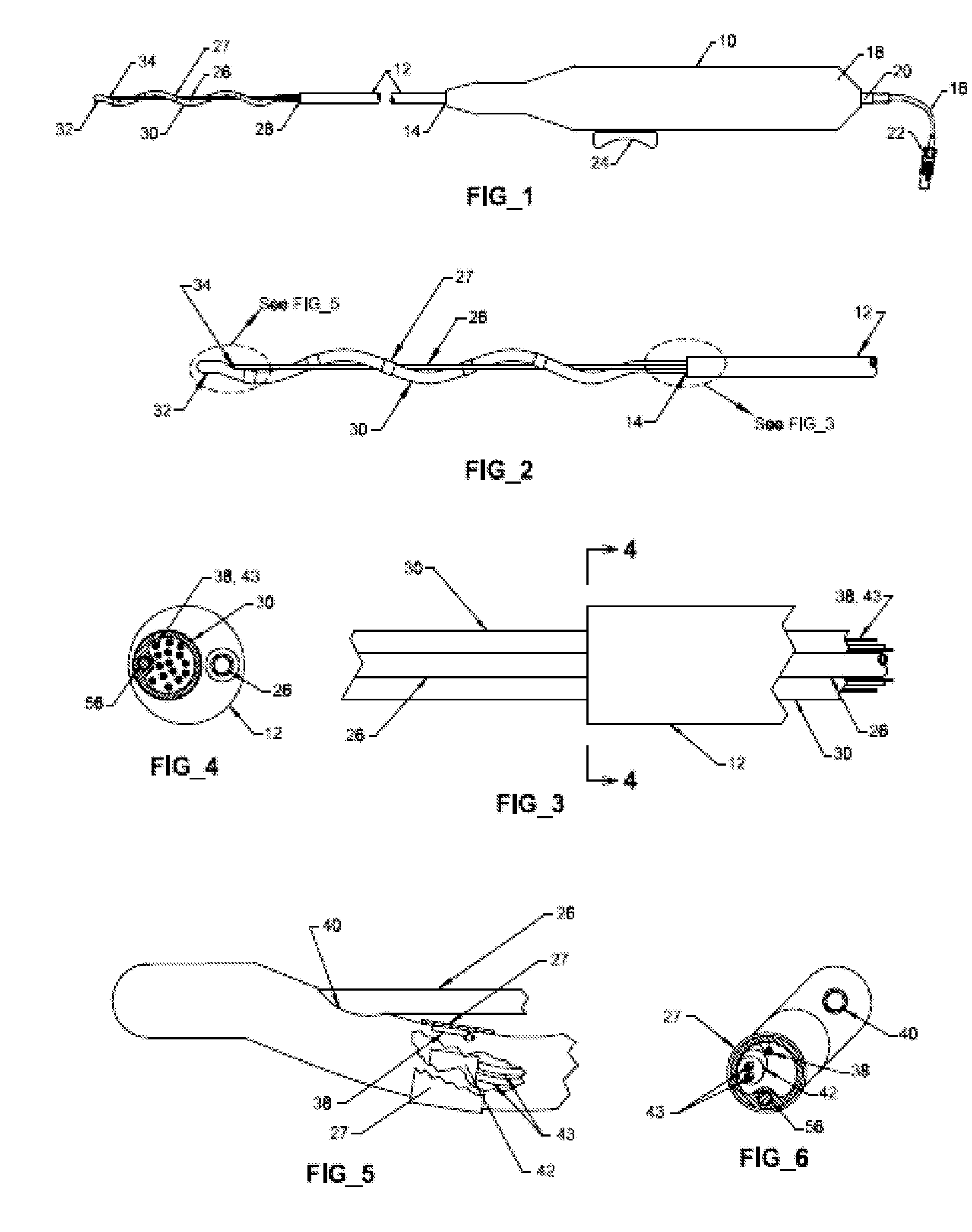
[0027]Referring now to FIG. 1 of the Drawing, a DNA catheter apparatus in accordance with the present invention is shown to include a handle 10 having a polymeric tubular proximal shaft 12 attached to and extending from one end 14, and a cable assembly 16 extending from the other end 18 through a polymeric strain relief fitting 20 and terminating in a suitable electrical connector 22. The handle 10 also serves as a housing for a relatively simple actuating mechanism, to be described below, which links a plastic or metallic slider 24 disposed in a slideable relationship with a slot (not shown) formed along a bottom portion of the length of the handle. The slider is operatively connected to a flexible tube or rod 26 made of a plastic or metallic material and extending out of the handle and through the flexible proximal shaft 12, and is internally in a forced contact with a frictional pad (not shown) mounted on a wall of the handle so as to auto-lock the slider at a desired position.

[0...

second embodiment

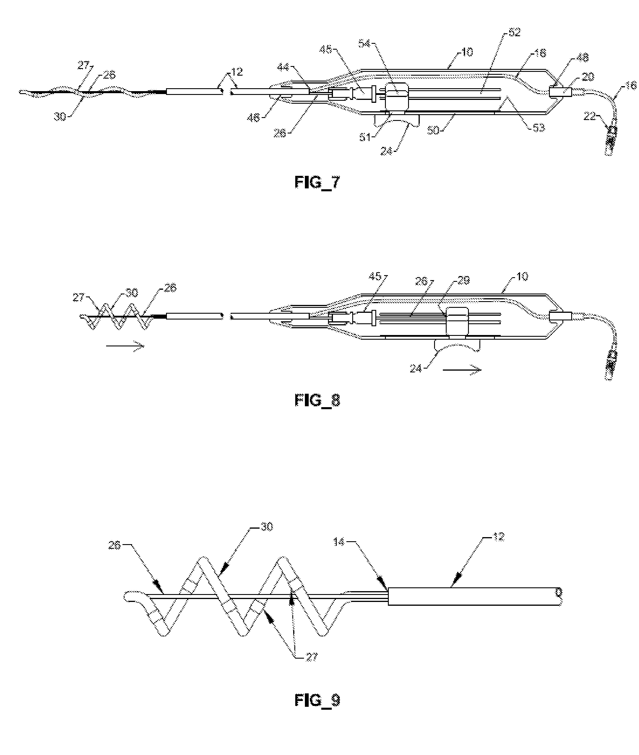
[0038]Functionally, in the first above described embodiment, the helically-coiled distal shaft tubing is designed to be extended in its rest or relaxed state, and is then compressed, as needed to deploy the several contacts into engagement with an endoluminal surface to be treated, by moving the slider rearwardly within the handle. But in the second embodiment, the helically-coiled-distal shaft tubing is designed to be compressed when in its rest or relaxed state, and to be extendable into an operating disposition by moving the slider forward. In each case, the extended state is for accommodating insertion of the catheter into an artery to be treated, and the retracting action is for adjusting, expanding and fitting the helix of the helically-coiled distal shaft and its carried electrodes within the artery.

[0039]Clinically, the helically-coiled ablation catheter, in an extended state, will be inserted into a femoral artery and advanced into a renal or other artery to be treated or a...


PUM


Abstract

A catheter apparatus carrying RF ablation electrodes on a helically configured portion of a flexible tube that can be inserted into the femoral artery of a patient, advanced into a renal artery, and then be manipulated to properly position electrodes carried by the helical tube to contact the endoluminal surface of the artery. While instrumentally monitoring the endoluminal surface's temperature and impedance (measured with electrodes that are in an intimate contact with the surface), a low level of RF energy can be applied to selected sites on the interior (endoluminal) surface of the artery in order to ablate the renal sympathetic nerves without affecting the abdominal, pelvic, or lower-extremity nerves.

Description

TECHNICAL FIELD[0001]The present invention relates generally to catheter apparatus and more specifically to a DNA catheter apparatus using radiofrequency (RF) energy to accomplish renal sympathetic denervation as a treatment for patients with drug-resistant hypertension.BACKGROUND[0002]Hypertension is associated with high rates of cardiovascular disease and death. Patients with a high blood pressure are treated with a variety of antihypertensive drugs which have increasingly shown to control their blood pressure. However, various studies indicate that the control rate remains suboptimal or the blood pressure is non-respondent or resistant to the drug treatment for a subset of population.[0003]Resistant hypertension is a failure to achieve a targeted level of blood pressure in patients who adhere to full tolerated doses of an appropriate three-drug regimen. Large clinical trials suggest that about 20% to 30% of hypertensive patients have resistant hypertension. For such patients, non...

Claims


Application Information

Patent Timeline
Patent Type & Authority Applications(United States)
IPC IPC(8): A61B18/14
CPCA61B18/1492A61B2018/00434A61B2018/1435A61B2018/00577A61B2018/00404A61B2018/00214A61B2018/00345A61B2018/00797
Inventor MOGUL, JAMIL
Owner MOGUL ENTERPRISES
Learn More