Supercharge Your Innovation With Domain-Expert AI Agents!

Transmitter module outputting wavelength multiplexed light

a transmitter module and wavelength multiplexing technology, applied in the field of transmitter optical modules, can solve the problems of degrading the high frequency performance of the transmitter module and increasing the transmission impedan

Active Publication Date: 2015-05-14
SUMITOMO ELECTRIC IND LTD
View PDF4 Cites 7 Cited by
  • Summary
  • Abstract
  • Description
  • Claims
  • Application Information

AI Technical Summary

Benefits of technology

The present patent application relates to a transmitter module that includes a plurality of laser diodes (LDs), a driver, a top carrier, and a box-shaped housing. The LDs emit optical beams with different wavelengths. The driver includes driving circuits for the LDs. The top carrier mounts inductors that provide bias currents to the LDs. The housing encloses the LDs, driver, and top carrier. The technical effect of this design is that the driver mounts the top carrier, which simplifies the assembly process and reduces the size of the transmitter module. Another design includes an LD with exposed electrodes, a driver with signal and ground pads, and a sub-mount with a relay pad and a die-pad. The anode electrode of the LD is wire-bonded to the signal pad of the driver through the relay pad on the sub-mount, and the cathode electrode of the LD is directly wire-bonded to the ground pad of the driver without being connected to the chassis ground of the housing. This design simplifies the assembly process and reduces the size of the transmitter module.

Problems solved by technology

A longer bonding wire causes an increase of the transmission impedance and degrades the high frequency performance of the transmitter module.

Method used


Image

  • Transmitter module outputting wavelength multiplexed light
  • Transmitter module outputting wavelength multiplexed light
  • Transmitter module outputting wavelength multiplexed light

Examples


Embodiment Construction

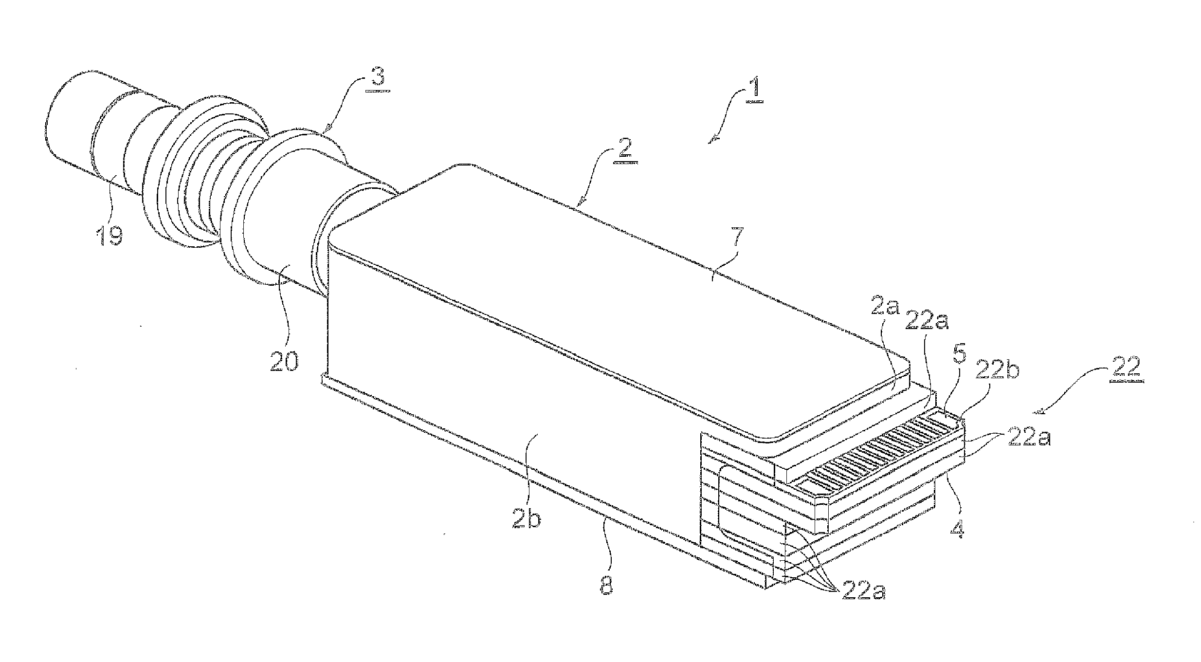
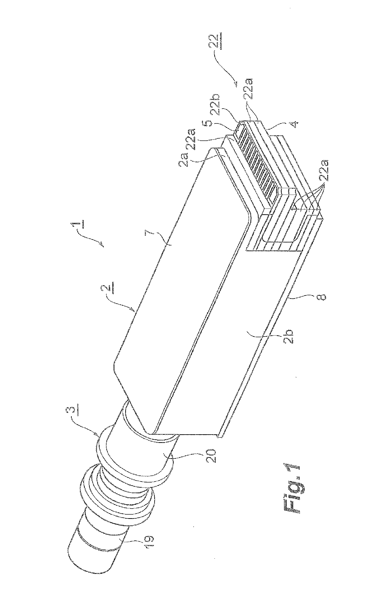
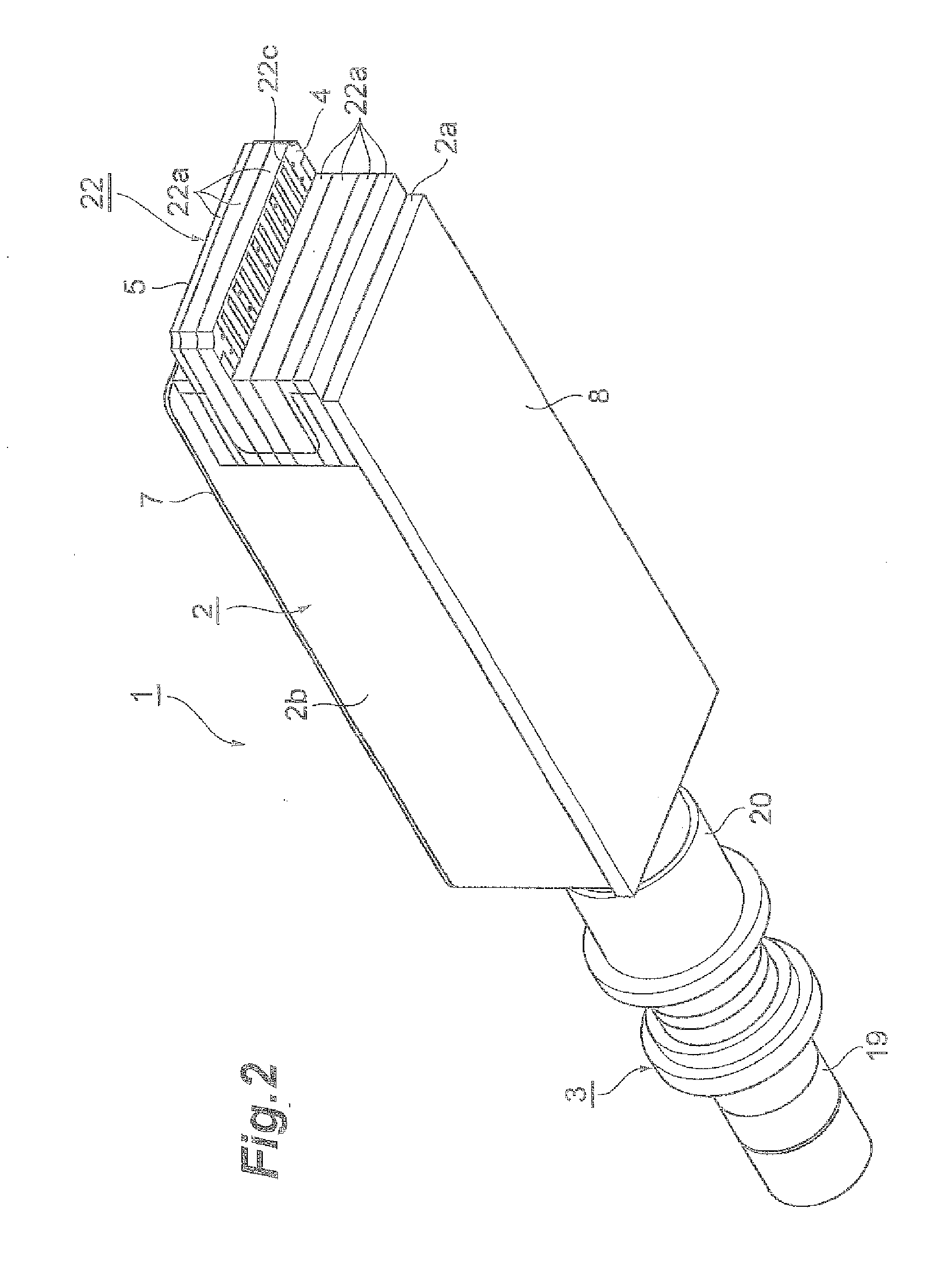
[0025]Next, some embodiments of a transmitter module of the present application will be described as referring to drawings. In the description of the drawings, numerals or symbols same with or similar to each other will refer to the elements same with or similar to each other without duplicating explanations.

[0026]A transmitter module such as that shown in FIG. 1 is necessary to match characteristic impedance of the transmission lines to enhance and secure high frequency performance. Such a transmission line is known as a micro-strip line and / or a co-planar line whose width of the conductive line and thickness of a substrate on which the conductive line is formed are designed to set the characteristic impedance in 50Ω for the single line, or 100Ω for the differential arrangement.

[0027]However, the transmission lines prepared outside of the housing 2 of the transmitter module 1 are connected to the transmission lines in the housing 2 through electrical pads and bonding wires wire-bon...


PUM


Abstract

A transmitter module having a plurality of semiconductor laser diodes (LDs) as optical signal sources that emit optical respective optical beams with specific wavelengths different from other is disclosed. The transmitter module includes, in addition to the LDs, a driver to drive LDs in the shunt-driving configuration. Inductors through which the bias currents for the LDs are provided are mounted on the driver as interposing a spacer and a top carrier.

Description

BACKGROUND OF THE INVENTION[0001]1. Field of the Invention[0002]The present application relates to a transmitter optical module, in particular, a transmitter optical module having a plurality of optical signal sources.[0003]2. Background Arts[0004]An optical transmitter module that installs four laser diodes (herein after denoted as LDs) each emitting an optical beam with a specific wavelength different from others has been known in the field. In order to driver LDs installed within such a transmitter module, active devices, typically in integrated circuit (IC) implementing driver circuits to driver respective LDs, and passive devices of capacitors and inductors are inevitably installed within a housing of the transmitter module. In particular, when the operational speed of the LDs exceeds 10 Gbps, or reaches 25 Gbps, the assembly of such active and passive devices becomes a key factor for the transmitter module to show the designed performance. Moreover, recent trend for active opt...

Claims


Application Information

Patent Timeline
Patent Type & Authority Applications(United States)
IPC IPC(8): H04B10/50H04J14/02
CPCH04J14/02H04B10/503H04B10/504H04B10/506H04J14/0307
Inventor SATO, SHUNSUKE
Owner SUMITOMO ELECTRIC IND LTD
Features
  • R&D
  • Intellectual Property
  • Life Sciences
  • Materials
  • Tech Scout
  • Unparalleled Data Quality
  • Higher Quality Content
  • 60% Fewer Hallucinations
Learn More