Airbag for a vehicle occupant restraint system

a technology for occupant restraints and airbags, which is applied in the direction of vehicle components, pedestrian/occupant safety arrangements, textiles and paper, etc., can solve the problem of not being able to achieve a comparable effect, and achieve the effect of strong tensile

Active Publication Date: 2015-05-21
TRW AUTOMOTIVE GMBH
View PDF7 Cites 7 Cited by
  • Summary
  • Abstract
  • Description
  • Claims
  • Application Information

AI Technical Summary

Benefits of technology

[0005]Compared to this, it is the object of the invention to exert a strong tensile effect directed to the interior of the airbag on particular sections of the airbag upon inflation of an airbag.
[0011]What is most efficient is the desired draw-in of particular airbag sections, when the weaving threads movable in their longitudinal direction relative to the inlet and outlet points during inflation of the airbag, i.e. when the opposed fabric layers are spaced apart from each other, extend in zigzag between the two fabric layers. Such course can be achieved most easily in that the cross loops of the first fabric layer are arranged to be offset against the cross loops of the second fabric layer related to the longitudinal direction of the weaving threads.

Problems solved by technology

It is not possible to achieve a comparable effect by weaving threads which extend to be freely floating from one fabric layer to the other, but are fixed at the inlet and outlet points.

Method used


Image

  • Airbag for a vehicle occupant restraint system
  • Airbag for a vehicle occupant restraint system
  • Airbag for a vehicle occupant restraint system

Examples


Embodiment Construction

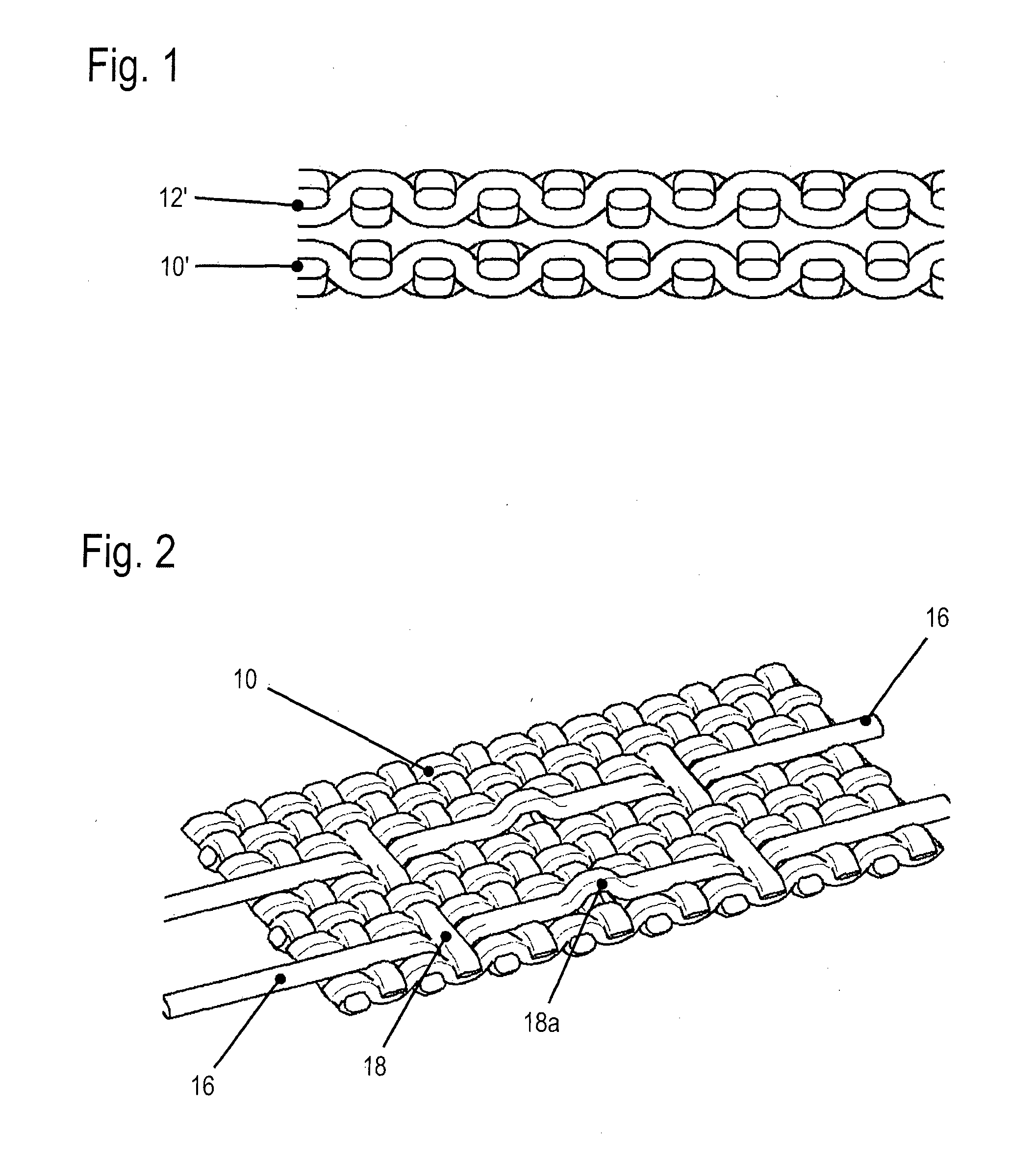
[0022]In FIG. 1 two fabric layers 10′ and 12′ of a so called “one-piece woven” airbag are shown each of which consists of a composite fabric of wefts and warps. The two fabric layers 10′, 12′ are woven on top of each other in one production step and are interconnected in one piece in a border area (not shown) by combining them into a very dense fabric. The border area delimits a chamber 14 formed between the fabric layers 10′, 12′ and adapted to be filled with gas. The chamber 14 can be the only one or one of plural chambers of the airbag.

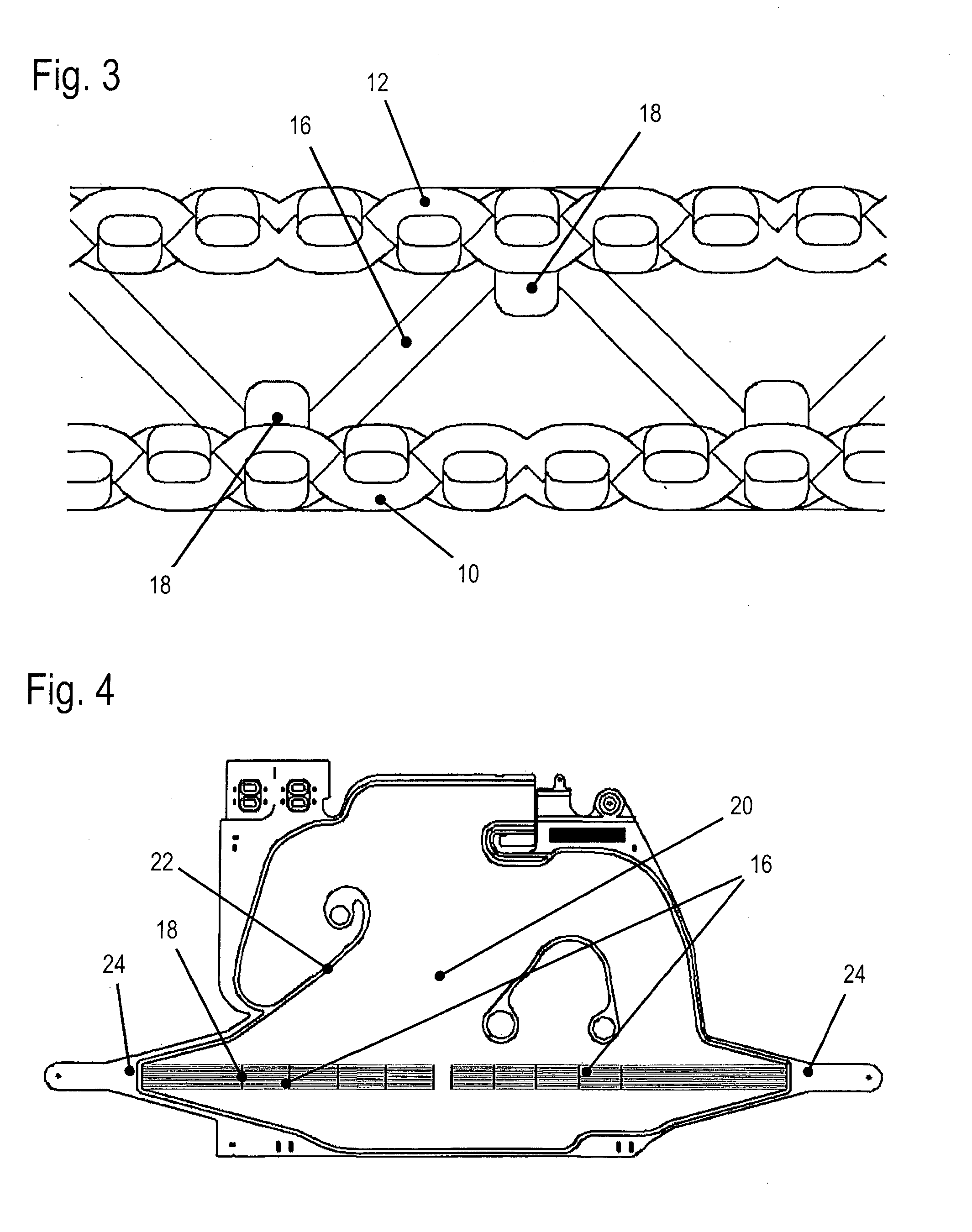
[0023]FIG. 2 shows a fabric layer 10 of an airbag according to the invention corresponding to the lower fabric layer 10′ of FIG. 1. Opposed thereto, a fabric layer 12 corresponding to the fabric layer 12′ is located, which fabric layer 12 was omitted here for the sake of clarity (but is shown in FIG. 3).

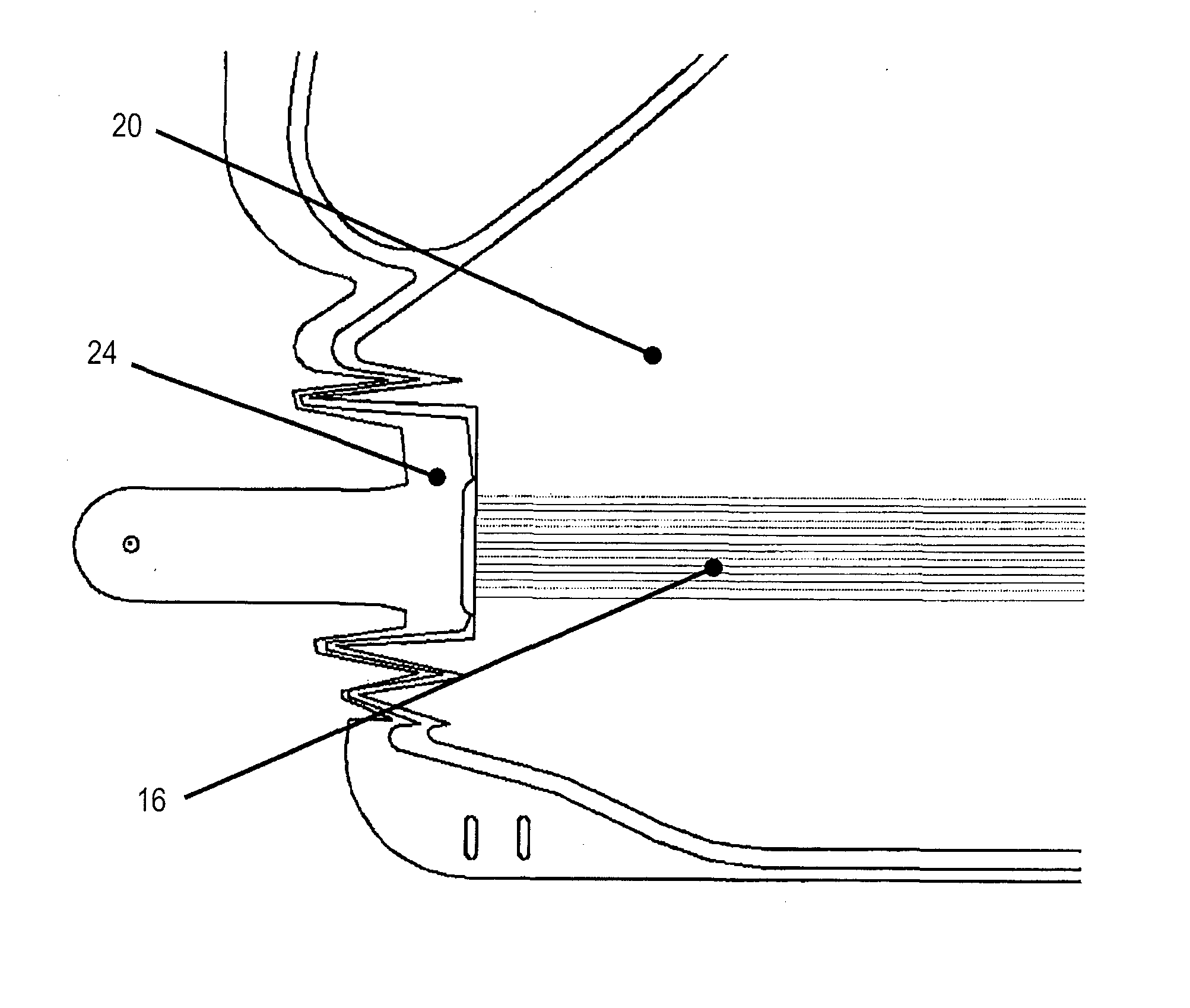
[0024]Individual weaving threads 16 spaced apart from each other extend loosely between the two fabric layers 10, 12 and at individual points only ...


PUM


Abstract

An airbag (20) for a vehicle occupant restraint system comprises a first fabric layer (10) and an opposed second fabric layer (12) each being formed of a composite fabric of wefts and warps and delimiting a chamber (14) adapted to be filled with gas. Plural weaving threads (16) are provided which exit the composite fabric of a fabric layer (10, 12) in the direction of the other fabric layer (12, 10) and are freely floating in the chamber (14) before they enter into the composite fabric of the other fabric layer (12, 10). The weaving threads (16) are movable in their longitudinal direction relative to the inlet and outlet points.

Description

RELATED APPLICATIONS[0001]This application corresponds to PCT / EP2013 / 001214, filed Apr. 23, 2013, which claims the benefit of German Application No. 10 2012 008 114.6, filed Apr. 25, 2012, the subject matter of which are incorporated herein by reference in their entirety,BACKGROUND OF THE INVENTION[0002]The invention relates to an airbag for a vehicle occupant restraint system.[0003]Airbags for vehicle occupant restraint systems are known in which two fabric layers are simultaneously manufactured and interwoven in one piece in the border area (“one-piece woven airbags” as they are called). Furthermore, specifically woven airbags are known in which individual weaving threads exit the composite fabric of a fabric layer close to the one-piece woven fabric section and enter into the composite fabric of the second fabric layer. These threads are intended to initially bring about a defined distance between the fabric layers upon inflation of the airbag. Moreover, these threads are to reli...

Claims


Application Information

Patent Timeline
Patent Type & Authority Applications(United States)
IPC IPC(8): B60R21/235
CPCB60R21/235B60R2021/23542B60R2021/23509B60R21/2334B60R2021/23538B60R2021/23571D03D1/02D03D11/02D03D13/00
Inventor FISCHER, ANTON
Owner TRW AUTOMOTIVE GMBH
Why Eureka
Try Eureka