Electromagnetic wave logging tool coil supporting and pulling device

A technology of well logging instrument and coil system, which is applied in electric/magnetic detection for well logging records, wellbore/well components, earthwork drilling and production, etc. It can solve the problem of increasing the cost of electromagnetic wave logging instruments and the structure of well logging instruments Complicated, inconvenient handling and disassembly, etc., to achieve the effect of not affecting the sensing area, saving manufacturing costs, and facilitating handling and disassembly

Inactive Publication Date: 2011-07-27
CHINA NAT OFFSHORE OIL CORP +1
View PDF6 Cites 2 Cited by
  • Summary
  • Abstract
  • Description
  • Claims
  • Application Information

AI Technical Summary

Problems solved by technology

Among them, the fiberglass skeleton drilling and pinning method has low tensile strength. When the tensile force is large, it is easy to crack at the pin hole, and the reliability is not high. The structure is complicated, the manufacturing cost is high, the weight of the instrument is heavy, and it is not easy to carry and disassemble. In addition, due to the conductivity of the metal inner core, the effective cross-sectional area of ​​the coil is reduced, and more coils need to be wound, which also increases the overall electromagnetic wave measurement. Cost of Well Instruments

Method used


Image

  • Electromagnetic wave logging tool coil supporting and pulling device
  • Electromagnetic wave logging tool coil supporting and pulling device
  • Electromagnetic wave logging tool coil supporting and pulling device

Examples


Embodiment Construction

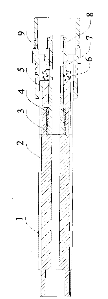
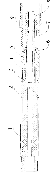
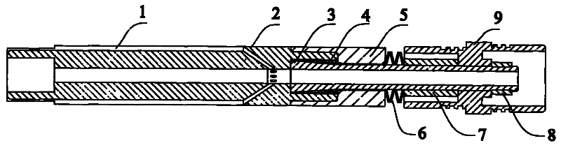
[0023] exist figure 1 In one embodiment of the present invention shown in , it also includes an outer tapered sleeve 4 matched with the inner tapered sleeve 3 , and the outer tapered sleeve 4 is arranged between the end of the bobbin 2 and the inner tapered sleeve 3 . The outer surface of the inner tapered sleeve 3 is a tapered surface, and the tapered surface is formed as a tapered surface whose outer diameter gradually decreases outward along the end of the inner tapered sleeve 3 close to the inner end of the inner hole at the end of the bobbin 2 . The inner surface of the outer tapered sleeve 4 is a tapered surface, and the tapered surface is a tapered surface whose inner diameter gradually decreases outwards along the end close to the inner end of the inner hole at the end of the bobbin 2 . The inner tapered sleeve 3 cooperates with the outer tapered sleeve 4 to form an inner metal ring, and extends into the inner hole of one end (first end) of the coil frame 2, so that th...


PUM


Abstract

An bearing and pulling device for electromagnetic wave logging instrument coil array comprises a coil rack, an inner cone sleeve is housed on the inner circumference side of the end of the coil rack and is housed for bearing and pulling the coil rack; a protective sleeve is housed on the outer circumference side of the end of the coil rack and is housed for cramping the coil rack. The bearing andpulling device for electromagnetic wave logging instrument coil array of the invention simplifies design of the bearing and pulling structure for electromagnetic wave logging instrument, meanwhile improves the bearing and pulling performance and reliability of the instrument, reduces manufacturing cost and is convenient for carrying and dismantling and mounting, with low failure rate and convenient maintenance.

Description

technical field [0001] The invention relates to the technical field of well logging, in particular to a coil system tension device of an electromagnetic wave logging instrument. Background technique [0002] Well logging is a downhole oil and gas exploration method, which is used to discover oil and gas reservoirs, evaluate oil and gas reserves and production, and it is also widely used in oil and gas field development and drilling engineering. Induction logging is a logging method that uses the principle of electromagnetic induction to study formation resistivity. [0003] The composition of the electromagnetic wave logging tool mainly includes a long, usually cylindrical coil frame, several transmitting coils and several receiving coils. At present, the coil frame of the electromagnetic wave logging instrument generally has a non-conductive glass steel pipe, a ring groove is opened on the outer peripheral surface of which the coil is wound on the groove, and a non-magneti...

Claims


Application Information

Patent Timeline
Patent Type & Authority Patents(China)
IPC IPC(8): G01V3/28E21B49/00
Inventor 卢达侯洪为秦才会
Owner CHINA NAT OFFSHORE OIL CORP
Why Eureka
Try Eureka