

Multiscreen display device
a multi-screen display and display device technology, applied in the field of multi-screen display devices, can solve the problems of inability to control a light source suitable, be separated, and lose the unity of a video image displayed on the entire multi-screen in some cases
- Summary
- Abstract
- Description
- Claims
- Application Information
AI Technical Summary
Benefits of technology
Problems solved by technology
Method used
Image

Examples
first preferred embodiment
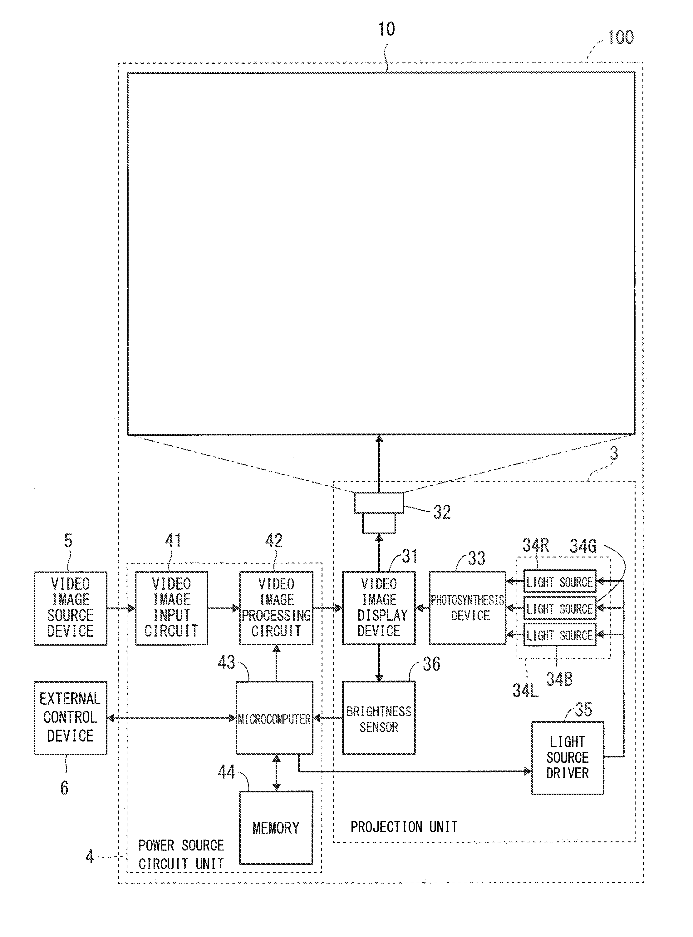
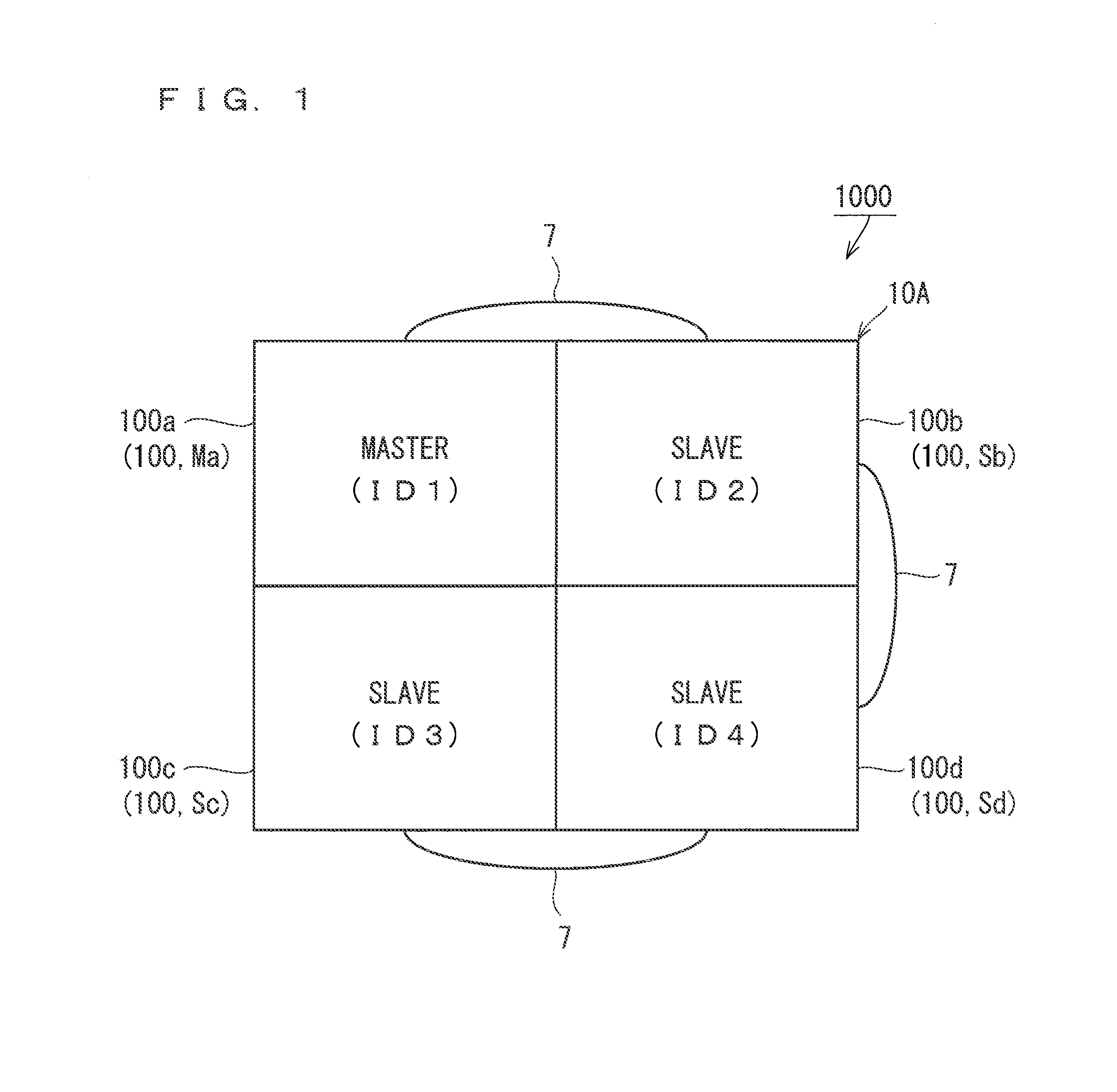
[0029]FIG. 1 is a view illustrating a configuration of a multiscreen display device 1000 according to a first preferred embodiment of the present invention. Although described in detail below, the multiscreen display device 1000 is formed with a plurality of projection video image display devices which can project video image lights which configure video images, on a screen. Further, the multiscreen display device 1000 is a device which displays a video image on a multiscreen which is formed with screens of a plurality of projection video image display devices which communicate with each other. The multiscreen display device 1000 will be more specifically described below.
[0030]As illustrated in FIG. 1, the multiscreen display device 1000 includes projection video image display devices 100a, 100b, 100c and 100d. Although described below in detail, each of the projection video image display devices 100a, 100b, 100c and 100d employs the same configuration. Each of the projection video ...
second preferred embodiment
[0194]Processing of suppressing brightness variations among a plurality of projection video image display devices 100 of a same brightness mode has been described with the first preferred embodiment. In this regard, a chromaticity value (chromaticity characteristics) of an LED corresponding to a control current value is different per LED due to, for example, manufacturing variations. Moreover, a control current value is not calculated taking into account a chromaticity in the first preferred embodiment. Therefore, the chromaticity is likely to vary more or less in a multiscreen display device1000 according to the first preferred embodiment.
[0195]Hence, a multiscreen display device according to the present preferred embodiment performs processing of enabling suppression of not only brightness variations but also chromaticity variations. In addition, the multiscreen display device according to the present preferred embodiment is the multiscreen display device 1000 in FIG. 1. Processin...
third preferred embodiment
[0292]Methods of reducing brightness and chromaticity variations of a multiscreen display device 1000 have been described with the first and the second preferred embodiments.
[0293]In the present preferred embodiment, processing of solving a failure which occurs when a user using the multiscreen display device 1000 changes a brightness mode of one of projection video image display devices 100 which form the multiscreen display devices 1000 will be described. The failure is a failure that most of brightnesses of the multiscreen display device 1000 change. When this failure occurs, the user feels uncomfortable.
[0294]First, processing (operation) which is likely to make the user feel uncomfortable will be described as a comparative example.
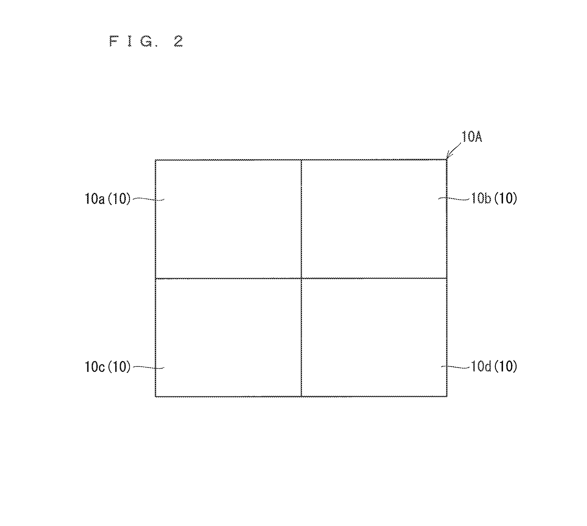
[0295]It supposes that the multiscreen display device 1000 is formed with the four projection video image display devices 100 as illustrated in FIG. 10 similar to FIG. 1. Further, each projection video image display device 100 performs one of above st...
PUM
 Abstract
Description
Claims
Application Information