
Camera module

a camera module and camera technology, applied in the field of optical devices, can solve problems such as affecting the reliability of image sensors

Active Publication Date: 2015-05-21
STMICROELECTRONICS INT NV
View PDF29 Cites 86 Cited by
  • Summary
  • Abstract
  • Description
  • Claims
  • Application Information

AI Technical Summary

Benefits of technology

The patent describes a camera module assembly and methods of making it. The assembly includes a substrate with an optical device attached to it. A molded body is attached to the substrate and over the optical device, with a recess for holding a lens assembly. A transparent material is then added over the lens assembly, which may be placed between the substrate and the lens assembly. The technical effect of this invention is an improved camera module assembly that allows for easier assembly and improved optical performance.

Problems solved by technology

Unfortunately, however, the air vent may also create an opening into a cavity that includes the image sensor, thereby exposing the image sensor to foreign material that can affect the reliability of the image sensor.

Method used


Image

  • Camera module
  • Camera module
  • Camera module

Examples


Embodiment Construction

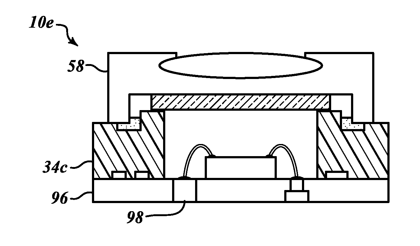
[0015]One or more embodiments are directed to optical module assemblies, such as camera module assemblies and methods of forming same. In one embodiment, the camera module assembly includes an optical device, such as an image sensor, on a first surface of a substrate and a lens assembly located above the optical device. As will be explained below, the camera module assembly has a first sealed chamber in which the image sensor is located and a second chamber formed in part by the lens assembly. The second chamber is fluidly isolated from the first chamber. The second chamber includes an air path for venting air during the lens assembly attachment process. By fluidly isolated the first chamber from the second chamber, the image sensor is protected from foreign objects that may enter into the second chamber through the air path.

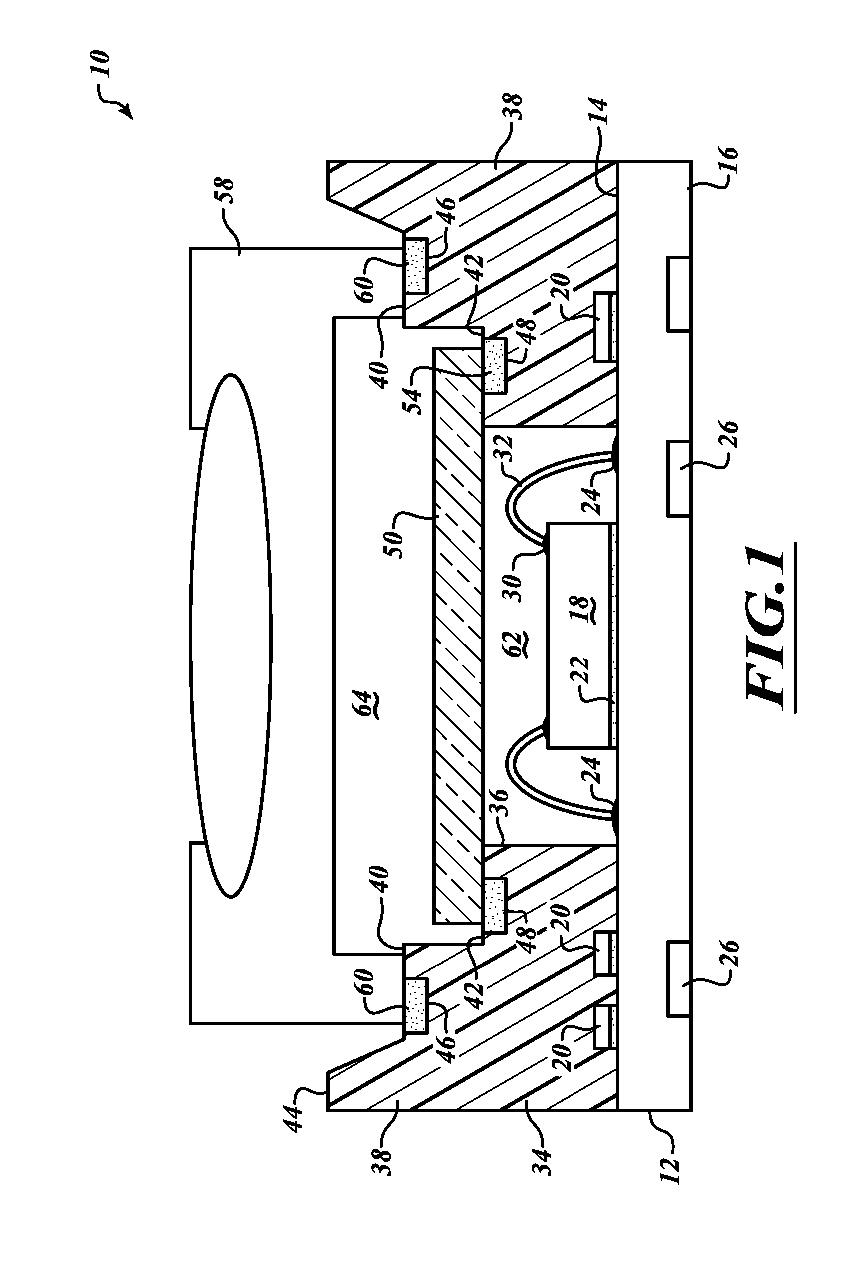
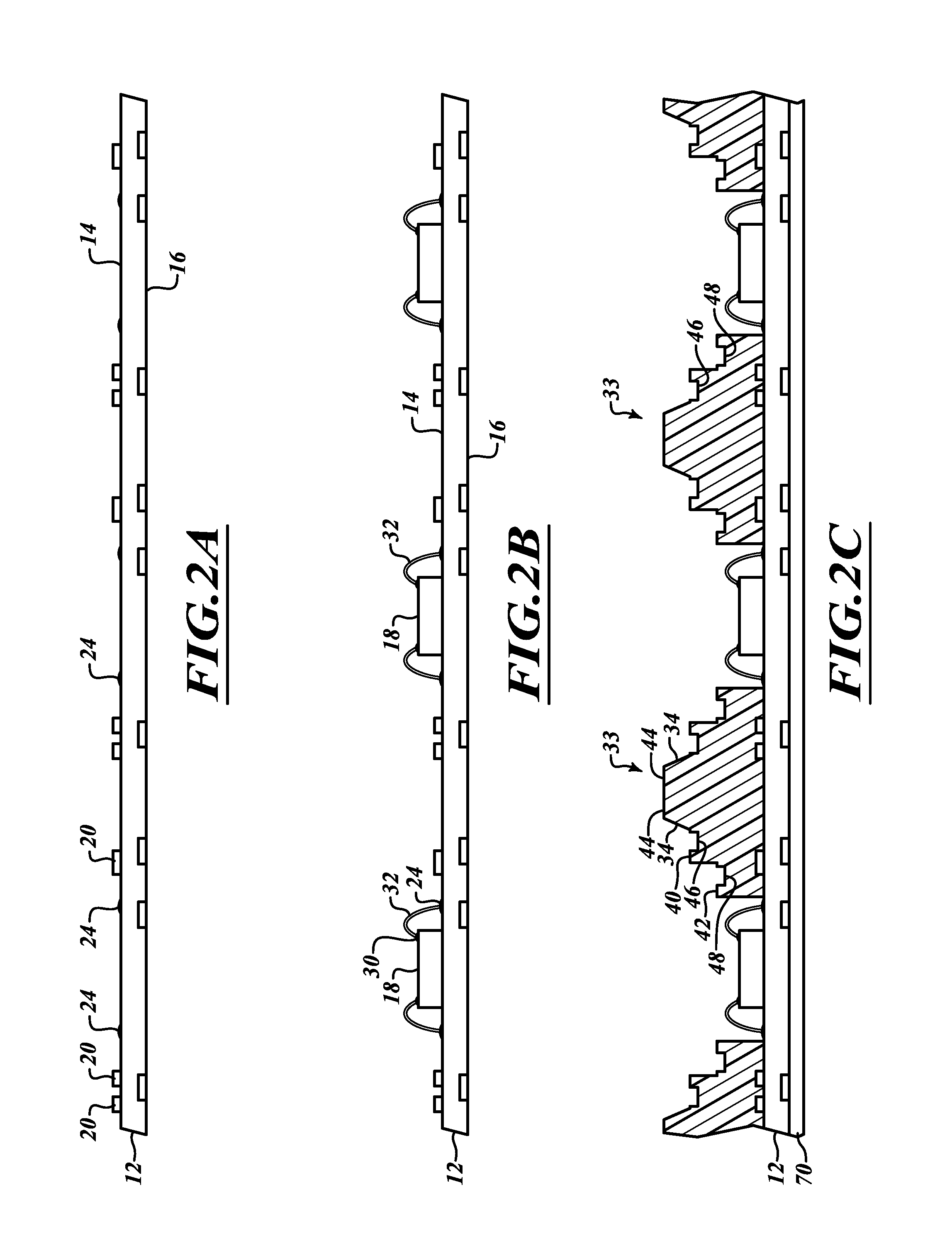
[0016]FIG. 1 shows a camera module assembly 10 according to one embodiment. The camera module assembly 10 includes a substrate 12 having a first surface 14 and ...


PUM

PropertyMeasurementUnit
conductiveaaaaaaaaaa
distanceaaaaaaaaaa
transparentaaaaaaaaaa

Abstract

One or more embodiments are directed to optical module assemblies, such as a camera module assembly, and methods of forming same. One embodiment is directed to an optical module assembly that includes a substrate having a first surface. An optical device is secured to the first surface of the substrate and electrically coupled to the substrate. A molded body is located on the first surface of the substrate outward of the optical device. The molded body includes a first recess. A lens assembly is secured to the molded body over the first recess by an adhesive material located in the first recess. In some embodiments, the molded body of the optical module assembly further includes a second recess spaced apart from the first recess. A transparent material is secured to the molded body over the second recess by an adhesive material located in the second recess.

Description

BACKGROUND[0001]1. Technical Field[0002]Embodiments of the present disclosure are directed to optical devices that include camera module assemblies.[0003]2. Description of the Related Art[0004]Camera module assemblies are used in various applications for capturing still images and videos. Such applications include smartphones, tablets, and cameras, which in general, have a consistent market demand for small and compact devices. In that regard, manufacturers are pressured to produce smaller electronic assemblies that are used in the various electronic devices.[0005]Generally described, camera module assemblies include a lens assembly located over an image sensor that may be attached to a substrate. Typically, the lens assembly is also attached to a surface of the substrate using a curing process, such as an ultraviolet (UV) light curing process. During the lens assembly attachment process, an air vent through the lens assembly allows air to escape. The air vent prevents a lens elemen...

Claims


Application Information

Patent Timeline
Patent Type & Authority Applications(United States)
IPC IPC(8): H04N5/225B29D11/00B29C65/48
CPCH04N5/2253B29C65/48B29L2031/764H04N5/2254B29D11/0074H01L27/14618H01L27/14683H01L24/97H01L2224/48091H01L2224/73265H01L2924/16195H04N23/54H04N23/57H01L2924/00014
Inventor WONG, WING SHENQ
Owner STMICROELECTRONICS INT NV
Features
  • Generate Ideas
  • Intellectual Property
  • Life Sciences
  • Materials
  • Tech Scout
  • Unparalleled Data Quality
  • Higher Quality Content
  • 60% Fewer Hallucinations
Learn More