Speaker Device

a technology of speaker device and speaker unit, which is applied in the direction of electrical apparatus, loudspeaker signal distribution, etc., can solve the problems of inability to specify which speaker unit is in failure, inability to easily realize failure, and inability to find abnormalities, so as to prevent the possibility of error detection and improve the accuracy of directivity control

a technology of speaker device and speaker unit, which is applied in the direction of electrical apparatus, loudspeaker signal distribution, etc., can solve the problems of inability to specify which speaker unit is in failure, inability to easily realize failure, and inability to find abnormalities, so as to prevent the possibility of error detection and improve the accuracy of directivity control

US20150139430A1Active Publication Date: 2015-05-21TOA CORP

Image

  • Speaker Device
  • Speaker Device
  • Speaker Device

Examples


embodiment 1

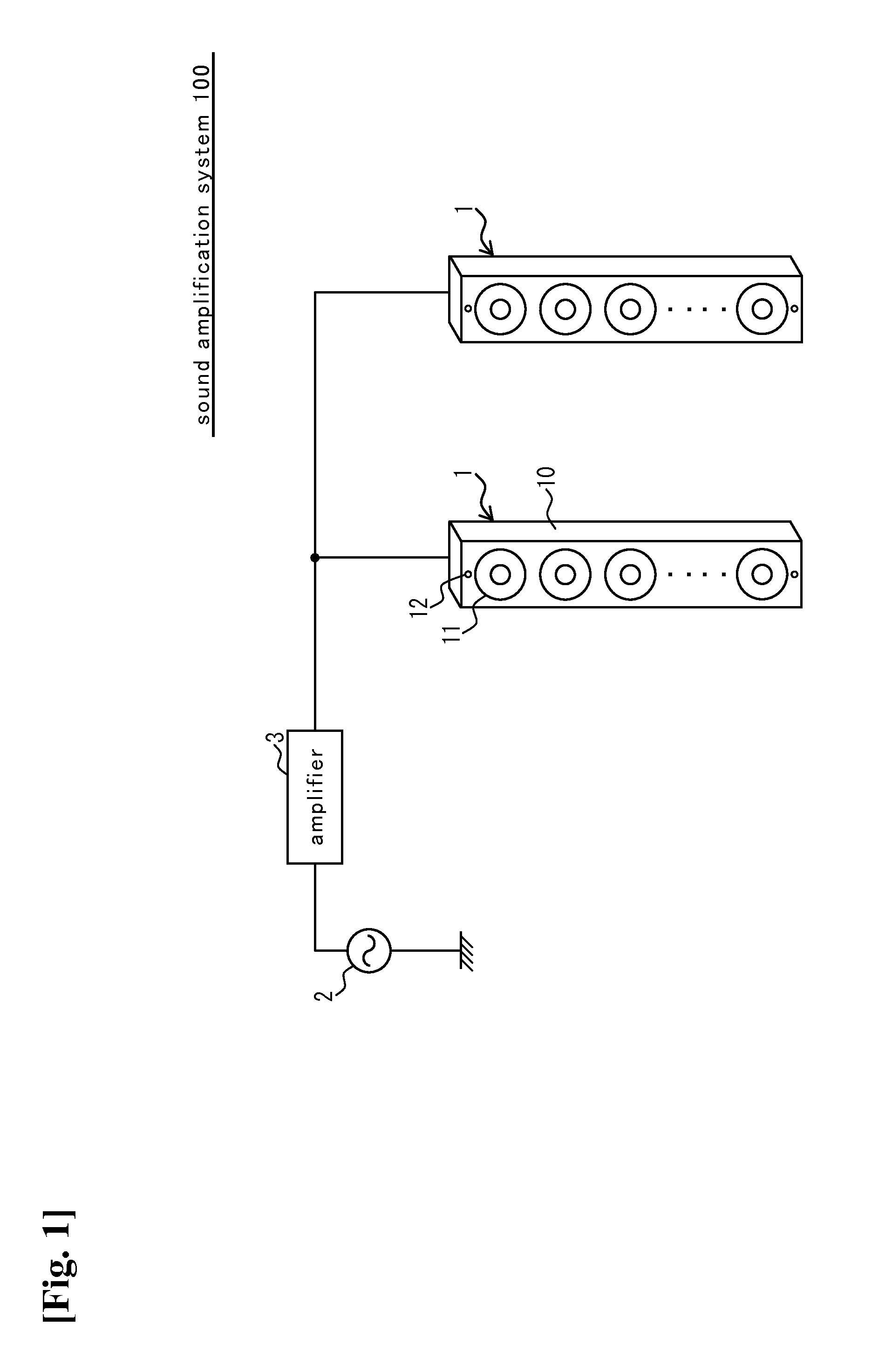
Sound Amplification System 100

[0039]FIG. 1 is a system diagram illustrating a configuration example of a sound amplification system 100 including array speaker apparatuses 1 according to Embodiment 1 of the present invention. The sound amplification system 100 is configured to include the two array speaker apparatuses 1, signal source 2, and amplifier 3, in which a broadcast signal generated in the signal source 2 is amplified by the amplifier 3, and the amplified broadcast signal is transmitted to the respective array speaker apparatuses 1.

[0040]For example, in the case of using a microphone as the signal source 2, a sound collection signal including frequency components in an audio band is generated in the microphone, and after amplified by the amplifier 3, transmitted to the respective array speaker apparatuses 1 as the broadcast signal. That is, the broadcast signal collected by the microphone is transmitted to the respective array speaker apparatuses 1, and inputted as an exter...

embodiment 2

[0076]In Embodiment 1, described is the example of the case where without interrupting sound emission based on the external sound signal 4, the failure detection is performed on the speaker units 11. On the other hand, in the present embodiment, described is the case where failure detection is performed on speaker units 11 using a test impulse signal.

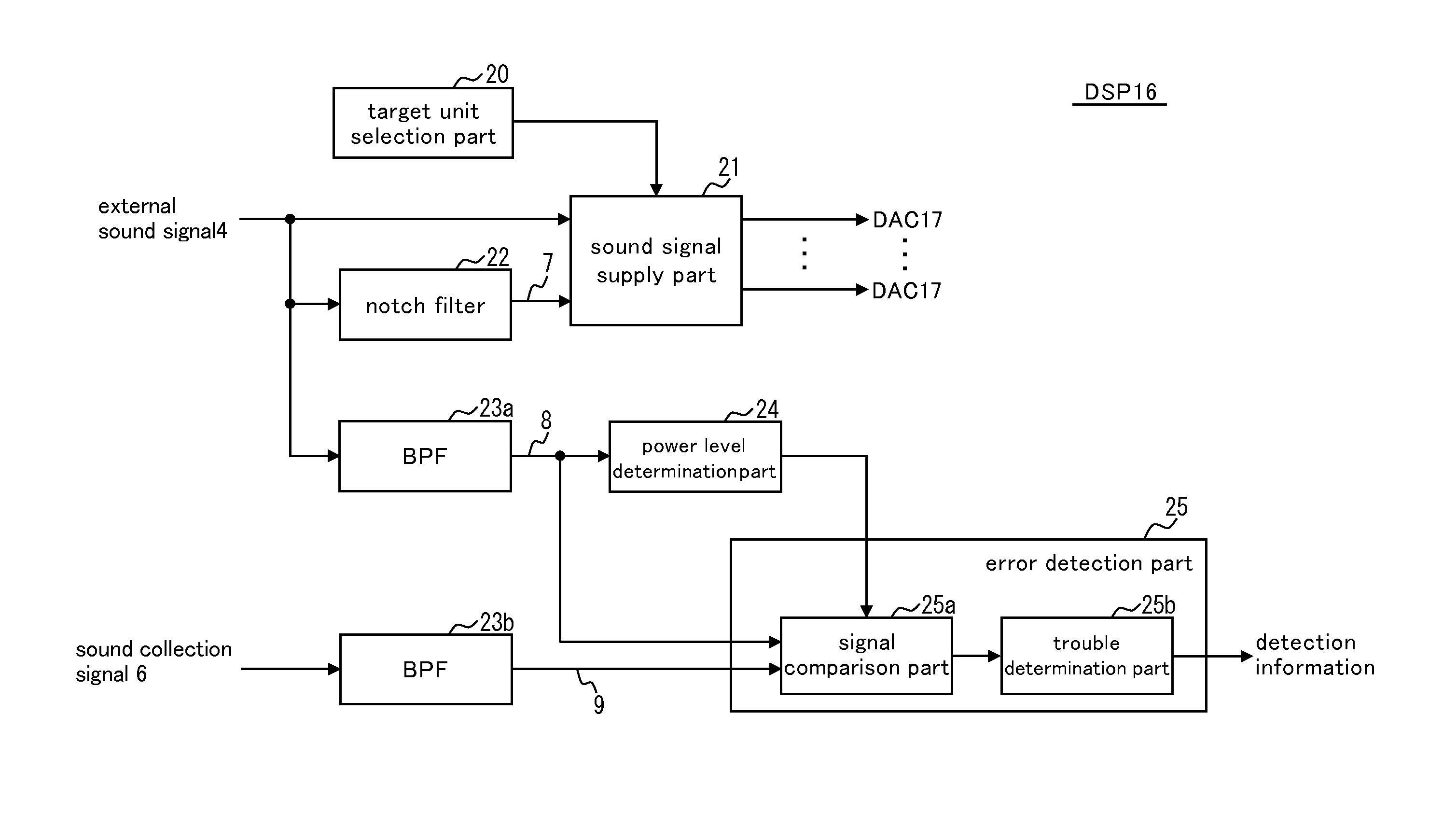
[0077]FIG. 5 is a block diagram illustrating a configuration example of an array speaker apparatus 1 according to Embodiment 2 of the present invention, in which an example of a functional configuration inside a DSP 16 is illustrated. The DSP 16 is configured to include a target unit selection part 20, a sound signal supply part 21, a test signal generation part 30, a sound signal comparison part 31, an error detection part 32, a frequency characteristics storage part 33, a sound velocity error calculation part 34, a physical distance storage part 35, and a directivity control part 36.

[0078]It is here assumed that the DSP 16 switches be...


PUM


Abstract

To provide a speaker apparatus that can detect miswiring to a speaker unit or trouble of a speaker unit itself. The speaker apparatus is configured to include: two or more speaker units 11 that are arranged in a speaker housing 10; a sensor microphone 12 that is arranged in the speaker housing 10 and outputs a sound collection signal 6; a target unit selection part 20 that selects any one of the speaker units 11 as a target unit; a sound signal supply part 21 that supplies an external sound signal 4 to the target unit; and an error detection part 25 that provides an error output on the basis of the external sound signal 4 and the sound collection signal 6.

Description

TECHNICAL FIELD[0001]The present invention relates to a speaker apparatus, and more specifically, to improvement of a speaker apparatus in which two or more speaker units are arranged in a speaker housing.BACKGROUND ART[0002]Speaker systems in which multiple speaker units are arranged in a speaker housing include one called an array speaker apparatus, which is sometimes used as a broadcast facility. As the array speaker apparatus, there is one that can control directivity of a sound wave by providing a delay circuit for each of speaker units and on a sound signal supplied to the speaker units, adjusting a delay time for each of the speaker units (e.g., Patent Literature 1).[0003]The respective speaker units of the above-described array speaker apparatus emit the same sound waves while producing slight time differences, and therefore even in the case where some of the speaker units are in failure, the failure cannot be easily realized. For example, even in the case where some of the ...

Claims


Application Information

Patent Timeline
21 May 2015
Publication
US20150139430A1
IPC
H04R29/00
CPC
H04R29/00; H04R3/12; H04R29/002
Inventors
MIYATA, SATOSHI; KUBOTA, HIROSHI