Silhouette-based object and texture alignment, systems and methods

a technology of object and texture alignment and silhouette, applied in the field of object recognition technology, can solve the problems of three-dimensional (3d) objects, failure to provide such features, and limited scope of technology

Active Publication Date: 2015-05-21
NANT HLDG IP LLC
View PDF20 Cites 49 Cited by
  • Summary
  • Abstract
  • Description
  • Claims
  • Application Information

AI Technical Summary

Benefits of technology

[0030]Various objects, features, aspects and advantages of the inventive subject matter will become more apparent from the following detailed description of preferred embodiments, along with the accompanying drawing figures in which like numerals represent like components.

Problems solved by technology

Unfortunately, such technologies are limited in scope and typically are only capable of recognizing a single object at a time (e.g., a single toy, a single person, a single graphic image, etc.).
The above referenced companies fail to provide such features.
For example, in the publication “Silhouette-Based Object Phenotype Recognition Using 3D Shape Priors” by Chen et al., published in the 2011 IEEE International Conference on Computer Vision, Nov. 6-13, 2011, Chen states that there is a fundamental problem in recognizing three-dimensional (3D) objects from one or more two-dimensional (2D) views in computer vision.
However, Chen takes a computationally intensive approach of generating large numbers of possible poses.
Unfortunately, such implementations are not suitable for mobile handheld devices and merely attempt to view shape as an identifier.
Mueller specifically points out the difficulty of prior techniques that scan for 2D color information and separately scan for 3D information.
However, such an approach fails to provide scale invariance when conducting recognition in handheld devices.
Although Lyon discloses adequate building of 3D models, such modeling information is not practical for full 3D object recognition or tracking on resource-constrained devices.
However, none of the references mentioned above provides an accurate 3D object recognition technique that is not computationally intensive, allowing real-time tracking of recognized objects.

Method used


Image

  • Silhouette-based object and texture alignment, systems and methods
  • Silhouette-based object and texture alignment, systems and methods
  • Silhouette-based object and texture alignment, systems and methods

Examples


Embodiment Construction

[0035]Throughout the following discussion, numerous references will be made regarding servers, services, interfaces, engines, modules, clients, peers, portals, platforms, or other systems formed from computing devices. It should be appreciated that the use of such terms is deemed to represent one or more computing devices having at least one processor (e.g., ASIC, FPGA, DSP, x86, ARM, ColdFire, GPU, multi-core processors, etc.) configured to execute software instructions stored on a computer readable tangible, non-transitory medium (e.g., hard drive, solid state drive, RAM, flash, ROM, etc.). For example, a server can include one or more computers operating as a web server, database server, or other type of computer server in a manner to fulfill described roles, responsibilities, or functions. One should further appreciate the disclosed computer-based algorithms, processes, methods, or other types of instruction sets can be embodied as a computer program product comprising a non-tra...


PUM


Abstract

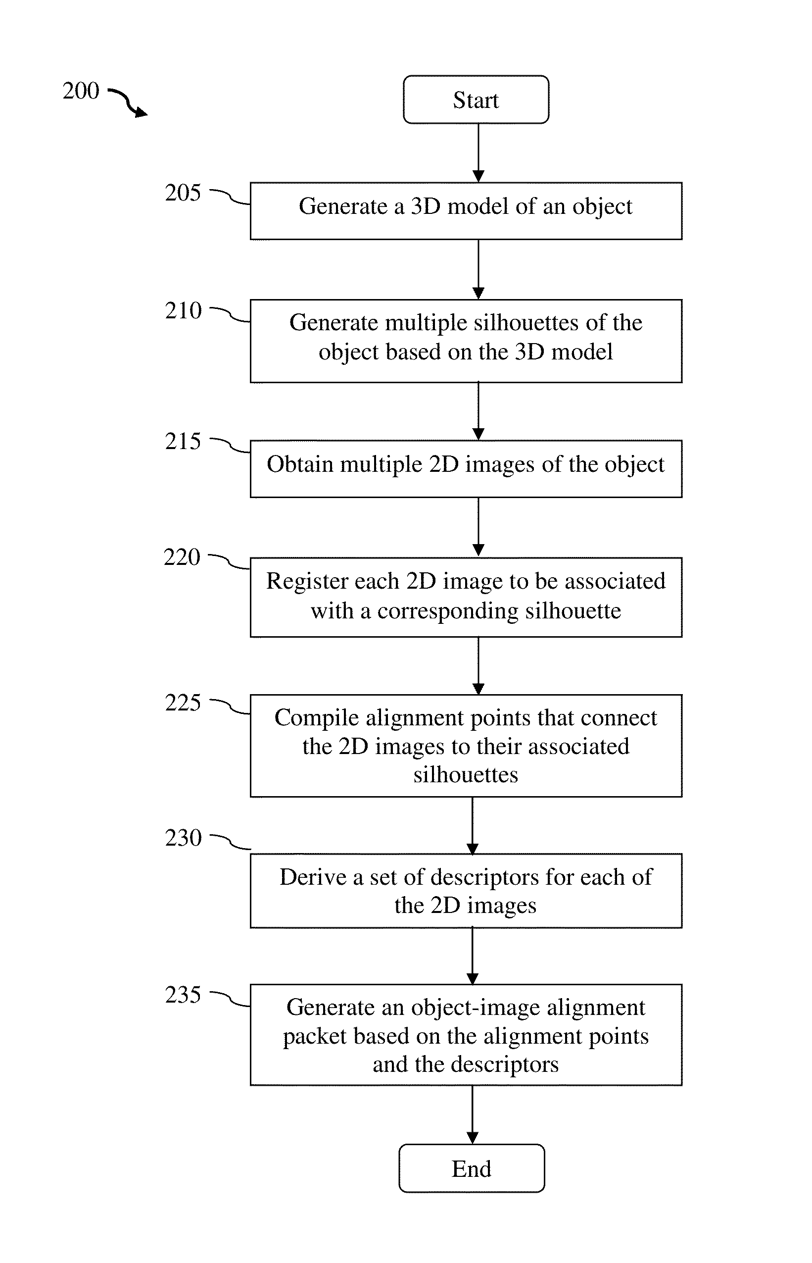
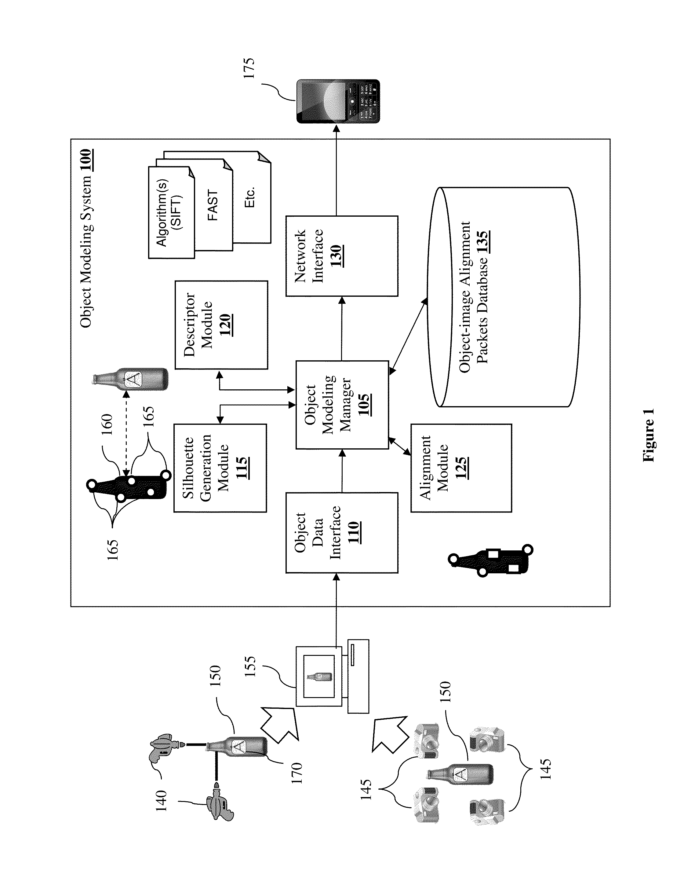
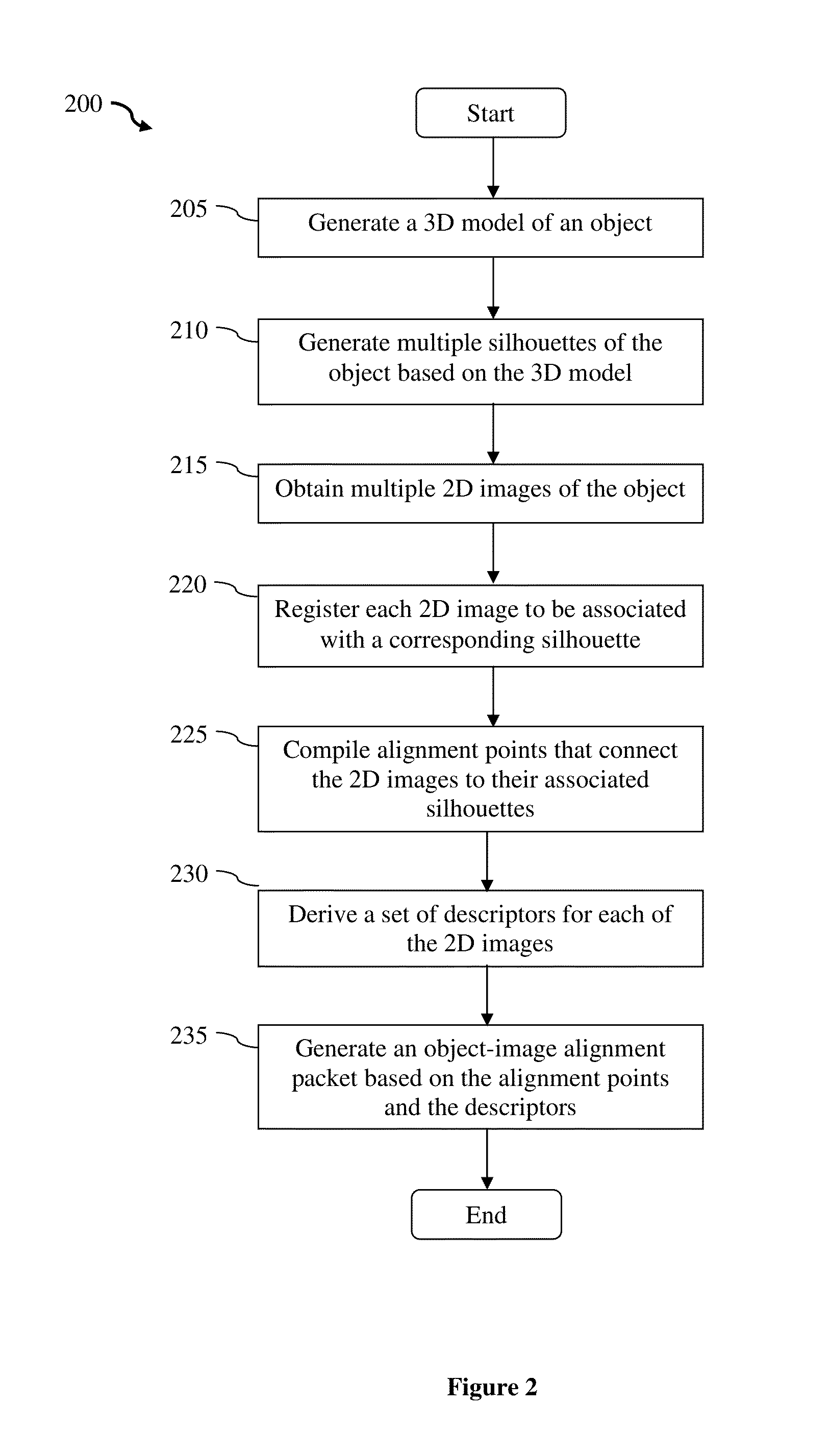
An object-image alignment data generating method for use in an object recognition system is presented. The method obtains a 3D model and a set of 2D images of the object. Each 2D image from the set is captured based on a particular camera point of view. The method then uses the 3D model of the object to generate multiple silhouettes of the object according to different camera point of views. Each silhouette is then matched and aligned with a 2D image based on the corresponding camera point of view. The method also derives at least one descriptor from the 2D images and compiles feature points that correspond to the descriptors. Each feature point includes a 2D location and a 3D location. The method then generates an object-image alignment packet by packaging the 2D images, the descriptors, and the feature points.

Description

[0001]This application claims priority to U.S. Application 61 / 905,575, filed Nov. 18, 2013. This and all other extrinsic materials discussed herein are incorporated by reference in their entirety. Where a definition or use of a term in an incorporated reference is inconsistent or contrary to the definition of that term provided herein, the definition of that term provided herein applies and the definition of that term in the reference does not apply.FIELD OF THE INVENTION[0002]The field of the invention is object recognition technology.BACKGROUND[0003]The following description includes information that may be useful in understanding the present invention. It is not an admission that any of the information provided herein is prior art or relevant to the presently claimed invention, or that any publication specifically or implicitly referenced is prior art.[0004]Consumers continue to experience an increasingly blurred distinction between real-world and on-line interactions. With the a...

Claims


Application Information

Patent Timeline
Patent Type & Authority Applications(United States)
IPC IPC(8): G06T7/00G06T15/20G06V10/772
CPCG06T7/0028G06T2207/10012G06T15/20G06T7/75G06T7/251G06V20/647G06V10/772G06F18/28G06T19/006
Inventor SIDDIQUI, MATHEEN
Owner NANT HLDG IP LLC
Why Eureka
Try Eureka