
Medical image-processing apparatus and a method for processing medical images

Inactive Publication Date: 2008-01-24
TOSHIBA MEDICAL SYST CORP
View PDF1 Cites 44 Cited by
  • Summary
  • Abstract
  • Description
  • Claims
  • Application Information

AI Technical Summary

Benefits of technology

[0014]The objective of the present invention is to solve the abovementioned problems and to provide a medical image-processing apparatus as well as a method for processing medical images, in order to reduce the time for aligning medical images with a high degree of accuracy.

Problems solved by technology

However, the following problems are involved in such conventional alignment methods described above.
This method is effective to some extent for two-dimensional images having small data volume, but for three-dimensional images having dramatically higher data volume, a long process time is required, so it can hardly be regarded as practical at the current stage.
Under such circumstances, it is expected to be difficult to achieve practical process time, even if a high-speed process method were to be added.
Meanwhile, in the alignment method using landmarks, there is a merit of shorter process time as described above, but there is difficulty in achieving accurate alignment.
Moreover, in reality, it is extremely difficult to attain an accurate graph representation of an object with a complex network such as pulmonary vessels.
This also has become a large obstacle in improving the accuracy of the alignment method using landmarks.
In particular, because accuracy is regarded as very important in the medical field in order to avoid medical errors, it is believed that the alignment method using landmarks has low usability.

Method used


Image

  • Medical image-processing apparatus and a method for processing medical images
  • Medical image-processing apparatus and a method for processing medical images
  • Medical image-processing apparatus and a method for processing medical images

Examples


specific example 1

[0145]The first specific example calculates the residual error when performing the coordinate transformation of landmarks based on the transformation parameter obtained by the transformation parameter-calculating part 51, and then removes the landmarks with the residual error that is a predetermined value or more, and calculates the transformation parameter again by using only the remaining landmarks.

[0146]An example of this process will be described in detail. The transformation parameter correction part 52 transforms the coordinate (ri, rj, rk) of each landmark r of the reference image to the coordinate (ti′, tj′, tk′) of the target coordinate system by using the transformation parameter obtained by the transformation parameter-calculating part 51.

[0147]Next is to calculate the difference Δ(r, t) between the coordinate (ti′, tj′, tk′) obtained by the transformation and the coordinate (ti, tj, tk) of the target coordinate system of the landmark t of the target image that has been c...

specific example 2

[0151]The second specific example corrects the transformation parameter by performing weighting on each of the landmark pairs using a weighted function (objective function) according to the difference Δ(r, t) that can be obtained similarly to the specific example 1.

[0152]FIG. 5 shows an example of the weighted function. The weighted function F shown in the same diagram is a nonlinear function, in which the value of gradient (slope) F′(Δ(r, t)) is large when the value of difference Δ(r, t) is small (when the residual error by the transformation parameter is small), and as the value of difference Δ(r, t) becomes larger, the value of gradient F′(Δ(r, t)) becomes gradually smaller. This weighted function F has, for example, gradient F′(Δ(r, t))=1 when the value of difference Δ(r, t) is small.

[0153]The transformation parameter correction part 52 is a non-linear optimization method using an iterative solution technique based on the weighted function F. Although this process uses the itera...

specific example 3

[0156]The third specific example is a modified version of the specific example 2. The characteristic of this specific example is that the weighted function (objective function) is modified in the iterating process of the non-linear optimization method using the iterative solution technique described in the specific example 2.

[0157]FIG. 6 shows an example of weighted function used in this specific example. The same diagram indicates two weighted functions F1 and F2. The weighted function F1 is used during the early phase of iterating process of the non-linear optimization method using iterative solution technique, and the weighted function F2 is used during the later phase of iterating process. The weighted function F2 is set in a way that the gradient F′Δ(r, t) becomes gradually smaller with a value of difference Δ(r, t) smaller than the weighted function F1.

[0158]The transformation parameter correction part 52 is configured to perform the process using the weighted function F1 unti...


PUM


Abstract

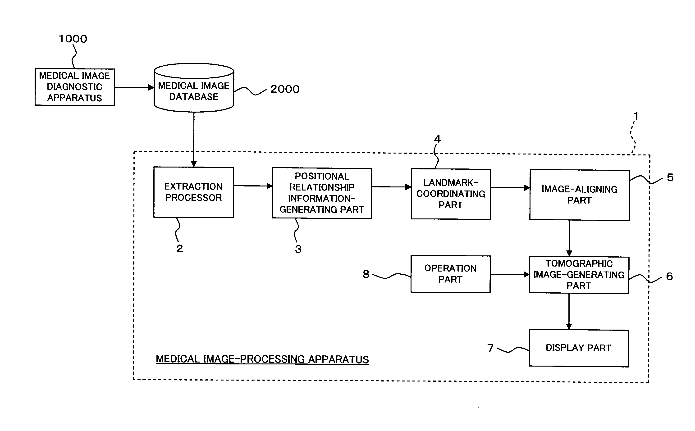
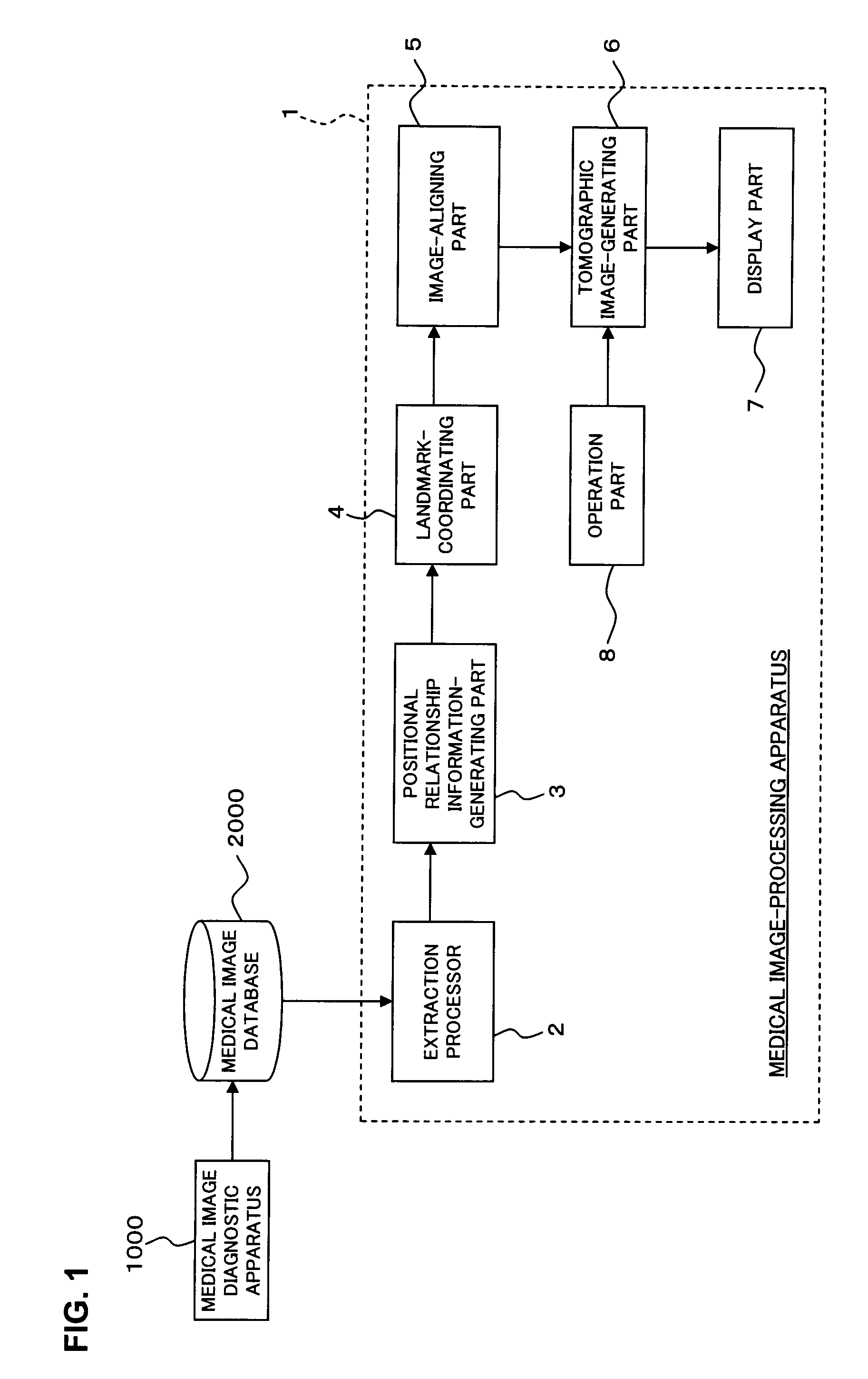
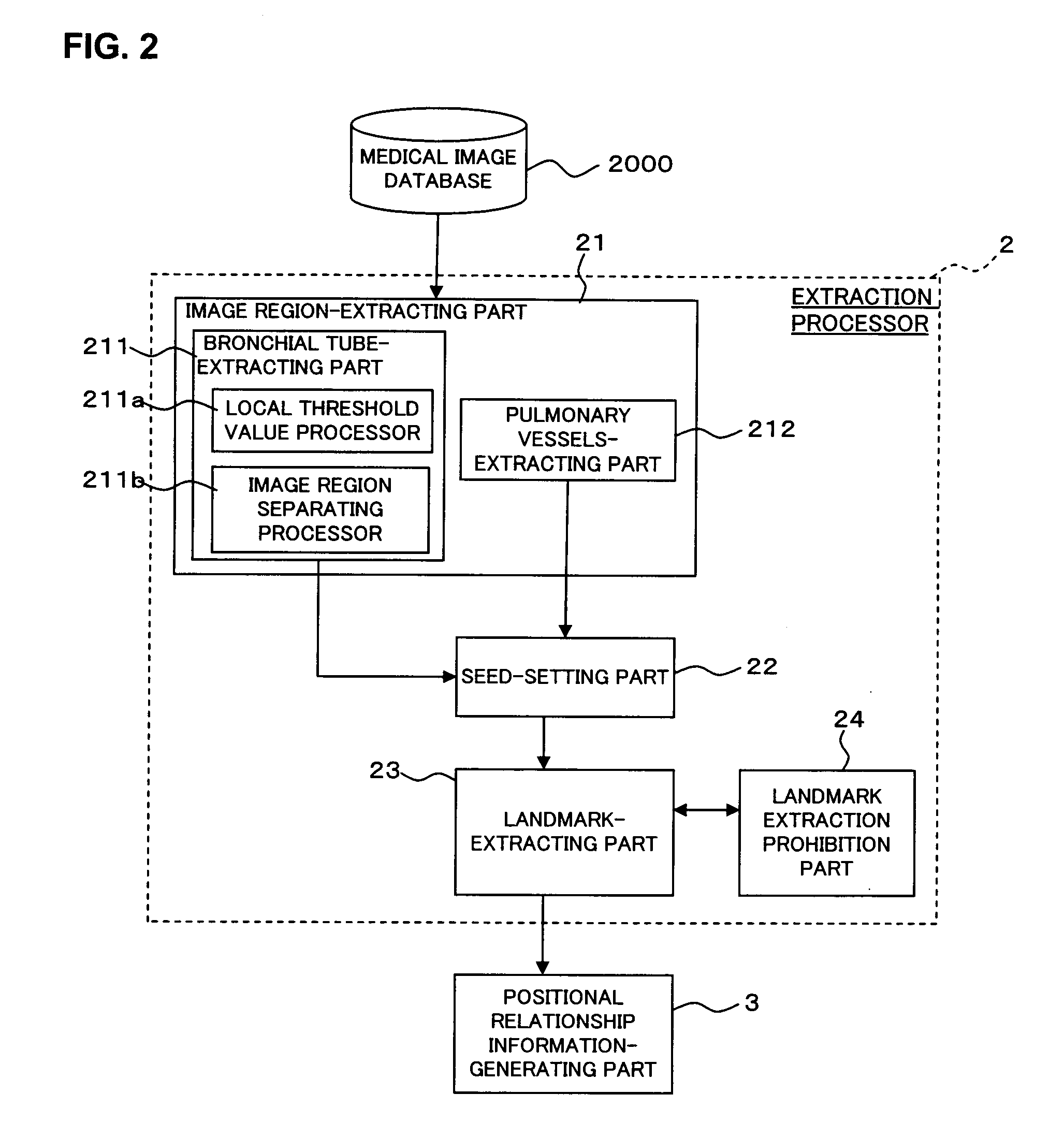
The extraction processor of the medical image-processing apparatus sets landmarks of each medical image based on volume data of two medical images. The positional relationship information-generating part generates positional relationship information that indicates positional relationship of the landmarks for each of the two medial images. The landmark-coordinating part eliminates one or more landmarks from each medical image based on the positional relationship information. Further, the landmark-coordinating part coordinates the landmarks of two medical images that remained after the elimination. The image-aligning part aligns the two sets of volume data based on the result of the coordination of landmarks.

Description

BACKGROUND OF THE INVENTION[0001]1. Field of the Invention[0002]The present invention relates to a medical image-processing apparatus and a method for processing medical images, for processing image data of medical images. In particular, the present invention relates to a technology for aligning two medical images (image data thereof).[0003]2. Description of the Related Art[0004]Conventionally, a plurality of medical images of a subject taken at different times has been compared to ascertain the progress of a disease or state of treatment for examination of treatment policy (e.g., refer to Japanese Patent Laid-Open No. 2005-334219). In such a comparative interpretation of radiograms, it is necessary to align images that have been taken at different times in order to compare slice images (such as CT image) at the approximately same position as the subject. Along with the introduction in recent years of apparatuses that can obtain three-dimensional medical images, alignment of three-d...

Claims


Application Information

Patent Timeline
IPC IPC(8): G06K9/32G06K9/00
CPCG06K9/3216G06T7/0038G06T7/0028G06T7/33G06T7/38G06V10/245
Inventor OHYU, SHIGEHARUYAMAGATA, HITOSHISUGIYAMA, ATSUKO
Owner TOSHIBA MEDICAL SYST CORP
Learn More