Image alignment method, comparative inspection method, and comparative inspection device for comparative inspections

a technology of image alignment and inspection method, applied in the field of image alignment method, comparative inspection method, and comparative inspection device for comparative inspection, can solve the problems of increasing the possibility of errors, increasing the probability of offset calculation error generation, and increasing the probability of offset error generation. , the effect of little or no dependency on pattern density or shape, and uneven luminance within individual images

Inactive Publication Date: 2006-03-28
HITACHI HIGH-TECH CORP
View PDF7 Cites 44 Cited by
  • Summary
  • Abstract
  • Description
  • Claims
  • Application Information

AI Technical Summary

Benefits of technology

[0008]The present invention provides a high-precision alignment method, device and code for inspections that compare an inspection image with a reference image and detect defects from their differences. In an embodiment an inspection image and a reference image are divided into multiple regions. An offset is calculated for each pair of sub-images. Out of these multiple offsets, only the offsets with high reliability are used to determine an offset for the entire image. This allows high-precision alignment with little or no dependency on pattern density or shape, differences in luminance between images, and uneven luminance within individual images. Also, detection sensitivity is adjusted as necessary by monitoring alignment precision. One embodiment of the present invention is suited for use in an alignment method implemented for visual inspection of semiconductor wafers. Other embodiments include use of a Semiconductor Electron Microscope, X-ray system, Focus Ion beam, Transparent Electron Microscope, and the like.
[0009]A second embodiment of the present invention provides a comparative inspection device including: a stage on which an object is mounted and which moves the object; a detector detecting an image of the object, the image including a plurality of small inspection image regions, and outputting an image signal; and an image processing unit for determining offsets for the inspection image regions when compared with corresponding reference image regions, and for determining an offset having a high reliability out of the offsets for the inspection image regions. The offset with high reliability is used to align an entire inspection image and an entire reference image.
[0011]A third embodiment of the present invention provides a method for aligning comparative inspection images including the following steps: an image detection step detecting an image of an object, the image having a plurality of inspection images of small regions, and outputting an image signal; an offset determining step determining offsets for the plurality of inspection images; an offset selection step selecting an offset with a high reliability; and a step for aligning an entire inspection image and an entire reference image using the offset with high reliability.

Problems solved by technology

However, in practice the stage may vibrate or the inspected object may be tilted so that the two images are not always aligned.
In all of these cases, there is a high probability that an offset calculation error will be generated.
Thus, methods that calculate offsets based on the information for entire images, as in the conventional technology, have a high probability that erroneous detections (false positives) will be generated by the offset.
Furthermore, the possibility of errors is increased even more if there is luminance shading within an image or if there is uneven brightness between images.
However, not all alignment errors cause a false detection.
In addition lowering the sensitivity, lowers the detection rate for true defects.

Method used


Image

  • Image alignment method, comparative inspection method, and comparative inspection device for comparative inspections
  • Image alignment method, comparative inspection method, and comparative inspection device for comparative inspections
  • Image alignment method, comparative inspection method, and comparative inspection device for comparative inspections

Examples


Embodiment Construction

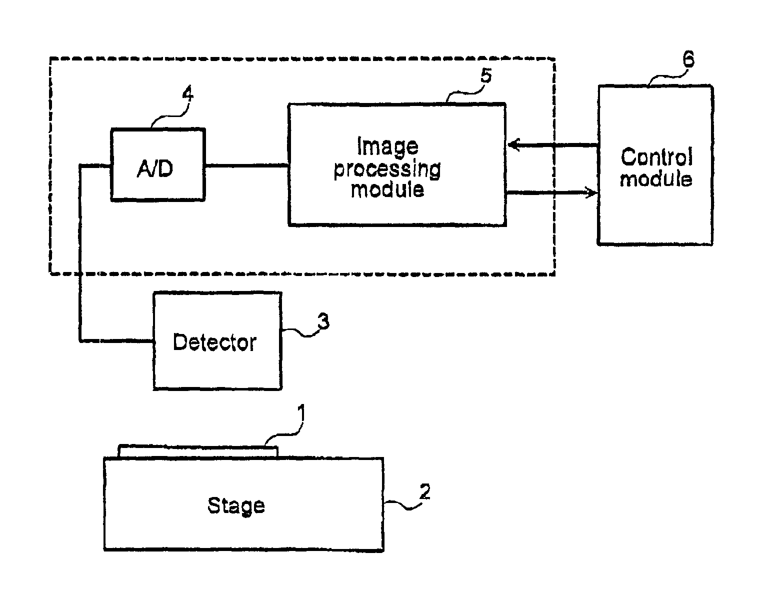
[0031]The following is a description of the embodiments of the present invention, with references to the figures.

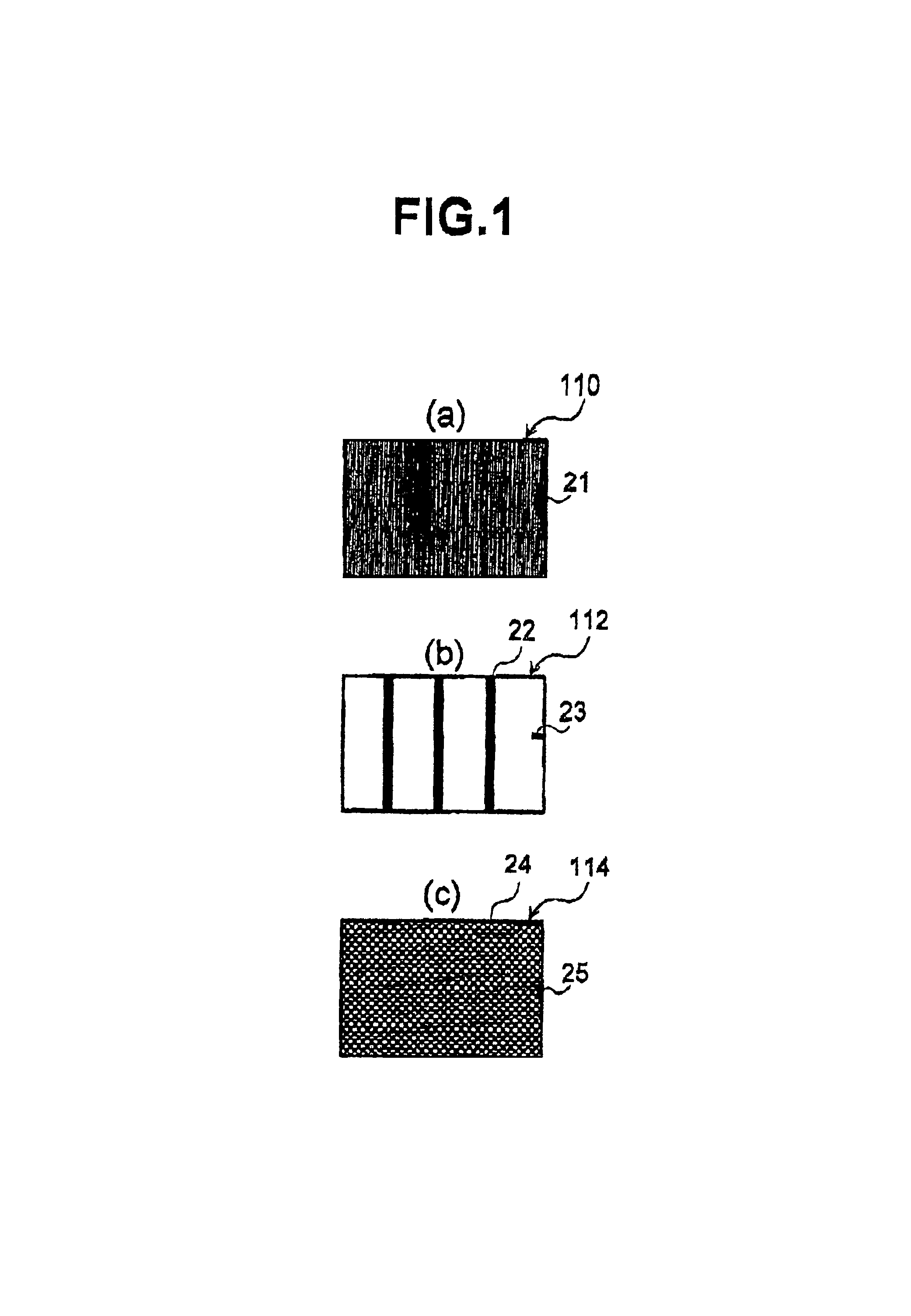
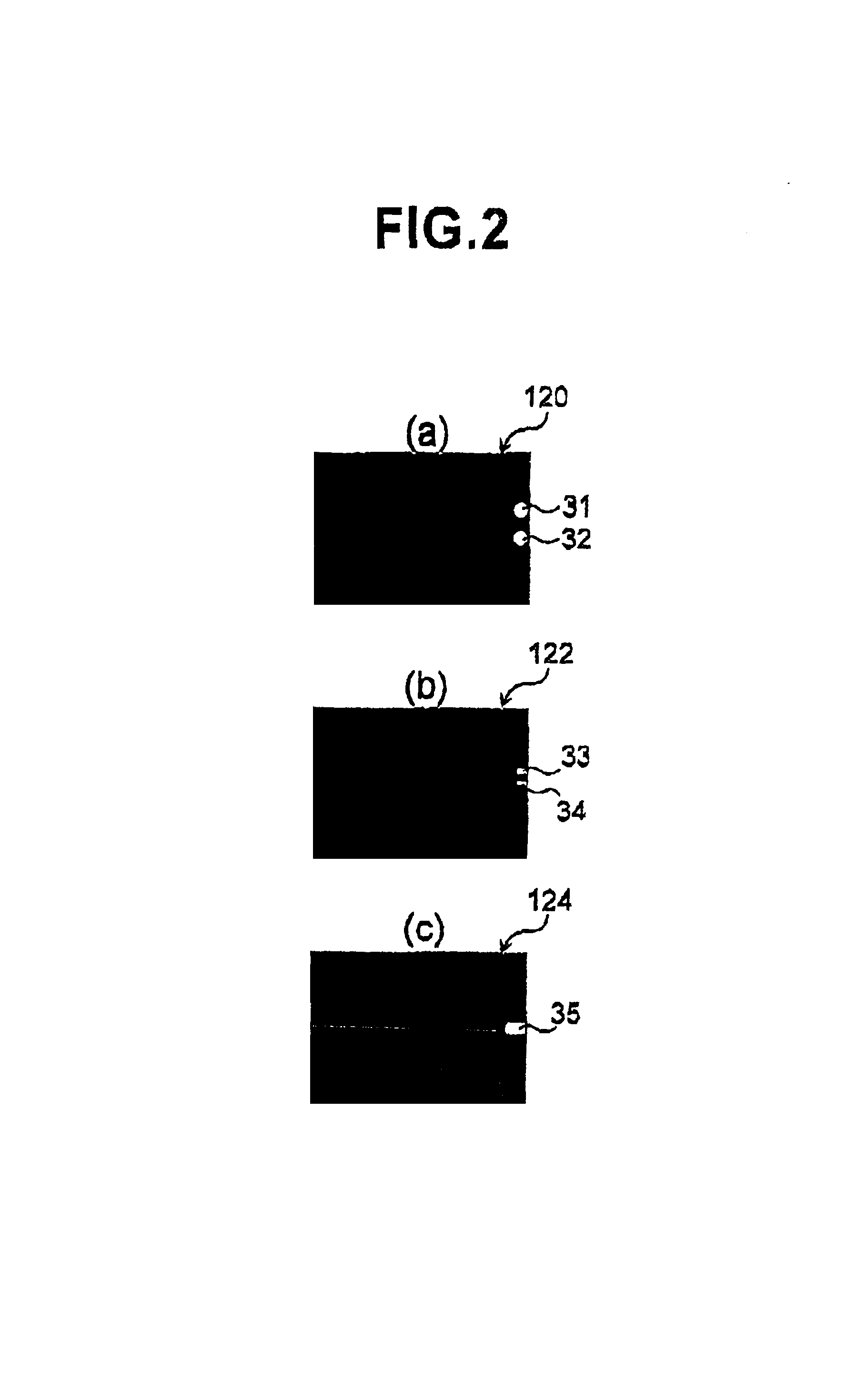
[0032]In the case of detecting misalignment between an image to be inspected, i.e., inspection image, and a reference image, the positional displacement or offset of the inspection image from the reference image is calculated so as to minimize the displacement of the edges between the images. However, as shown in FIG. 1 above there are several cases where there is a high probability of error in the offset calculation. Some of the cases are: 1) the edge density is low; 2) the number of edges in a specified direction is high, and 3) the number of repetitive patterns of fine pitch is high. Thus when the prior art method of calculating an amount of positional offset based on information about the entire image is used, there is a high probability of producing a false detection due to an incorrect offset at the location of the irregular pattern.

[0033]In order to show the reason...


PUM


Abstract

The present invention provides a high-precision alignment method, device and code for inspections that compare an inspection image with a reference image and detect defects from their differences. In one embodiment an inspection image and a reference image are divided into multiple regions. An offset is calculated for each pair of regions. Out of these multiple offsets, only the offsets with high reliability are used to determine an offset for the entire image. This allows high-precision alignment with little or no dependency on pattern density or shape, differences in luminance between images, and uneven luminance within individual images. Also, detection sensitivity is adjusted as necessary by monitoring alignment precision.

Description

CROSS-REFERENCES TO RELATED APPLICATIONS[0001]This application is related to and claims priority from Japanese Patent Application No 2000-184563, filed on Jun. 15, 2000.BACKGROUND OF THE INVENTION[0002]Japanese laid-open patent publication number Hei 05-264467 describes a known pattern inspection method in which defects are detected by comparing an inspection image and a reference image.[0003]In this method, a line sensor sequentially images an inspected object on which a repeated pattern is arranged in an orderly manner. A comparison is made with an image that has been delayed by a time interval corresponding to the pitch of the repeated pattern, and inconsistencies are detected as pattern defects. However, in practice the stage may vibrate or the inspected object may be tilted so that the two images are not always aligned. Thus, an offset must be determined for the image that has been delayed by the pitch of the repeated pattern. The two images are then aligned based on the determ...

Claims


Application Information

Patent Timeline
Patent Type & Authority Patents(United States)
IPC IPC(8): G06K9/32G01B11/00G06T1/00G06T7/00G06T7/60
CPCG01N21/95607G03F1/84G06T7/0026G06T7/001G06T2207/30148G06T7/32
Inventor SAKAI, KAORUMAEDA, SHUNJIOKABE, TAKAFUMI
Owner HITACHI HIGH-TECH CORP
Why Eureka
Try Eureka