Universal Carnot propulsion systems for turbo rocketry

a technology of propulsion system and carnot, which is applied in the direction of sustainable transportation, mechanical equipment, machines/engines, etc., can solve the problems of reducing the range of flight, and reducing the specific fuel consumption. , to achieve the effect of improving efficiency and improving specific fuel consumption

Inactive Publication Date: 2006-04-27
PAUL MARIUS A
View PDF0 Cites 42 Cited by
  • Summary
  • Abstract
  • Description
  • Claims
  • Application Information

AI Technical Summary

Benefits of technology

[0007] The revolutionary universal Carnot propulsion systems for turbo rocketry eliminate many technological barriers which have typically resulted in limited thermal efficiencies averaging 30% with pressure ratios of 25 / 1, air fuel ratios of 60 / 1 and thrust to weight ratios of 16 / 1, which generally use only 25% of the air compressed in the gas turbines.
[0009] For all alternatives, the main characteristic is the maximum absolute thermal efficiency of the Carnot thermal cycle, producing the maximum absolute range of flight for the available thermal source. For all alternatives, the final compression process is isothermal, with minimum work for compression and a minimum temperature at the end of the compression. For all alternatives, the combustion process cane achieve a maximum absolute isothermal and stoichiometric level, resulting in maximum power density and the maximum absolute thrust to weight ratio possible.
[0011] The revolutionary gas turbine Carnot cycle engines of this invention can operate at a constant isothermal temperature resulting in better efficiency and better specific fuel consumption at all loads of operation for extended flight.

Problems solved by technology

State-of-the-art gas turbines are not conserving the maximum turbine inlet temperature and pressure ratio of the cycle from full load to part loads, and are thereby losing the temperature and pressure ratios at part loads.
The corresponding loss of thermal efficiency results in raising the specific fuel consumption to unacceptable high levels and severely limits the range of flight.

Method used


Image

  • Universal Carnot propulsion systems for turbo rocketry
  • Universal Carnot propulsion systems for turbo rocketry
  • Universal Carnot propulsion systems for turbo rocketry

Examples


Embodiment Construction

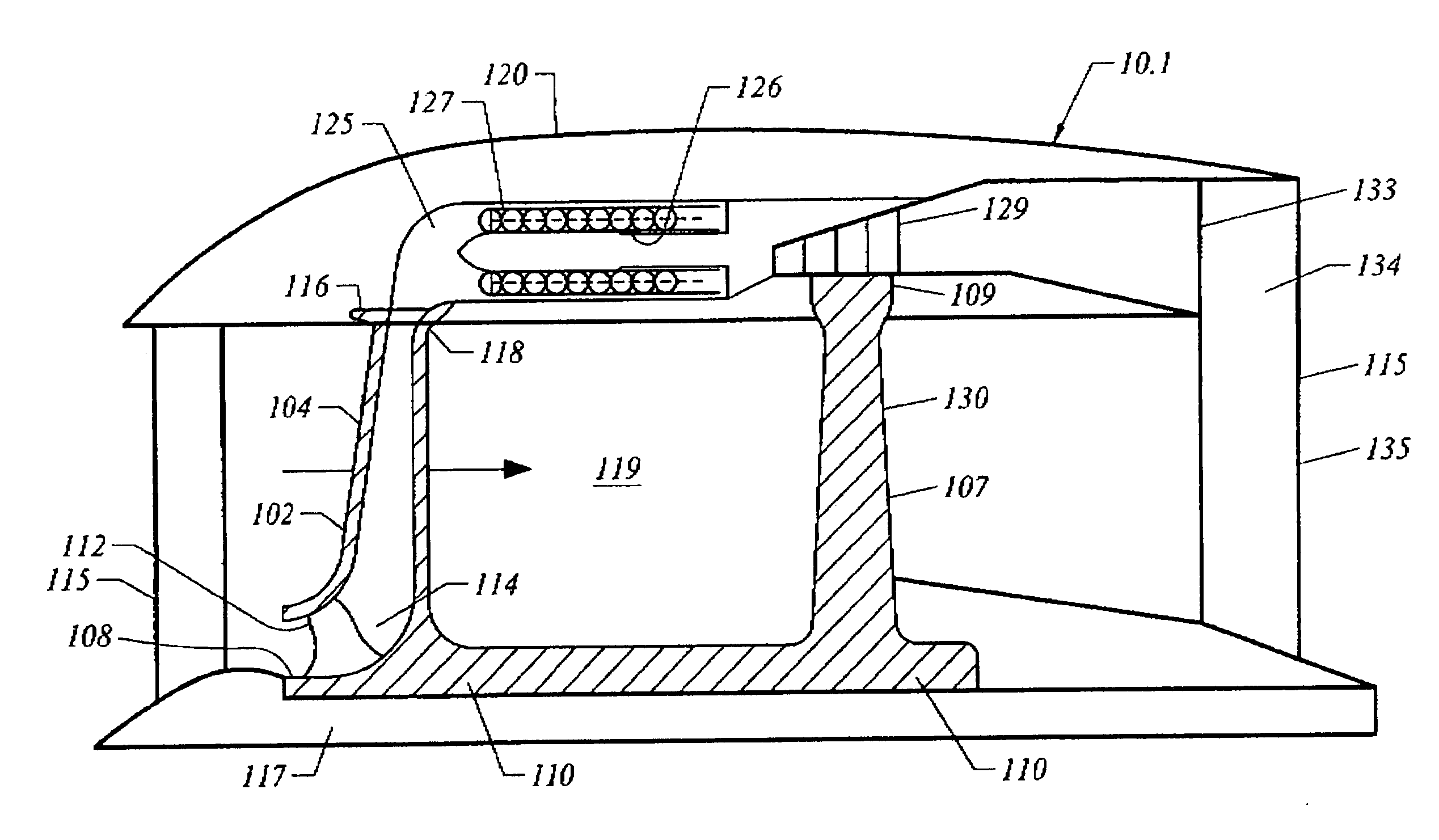
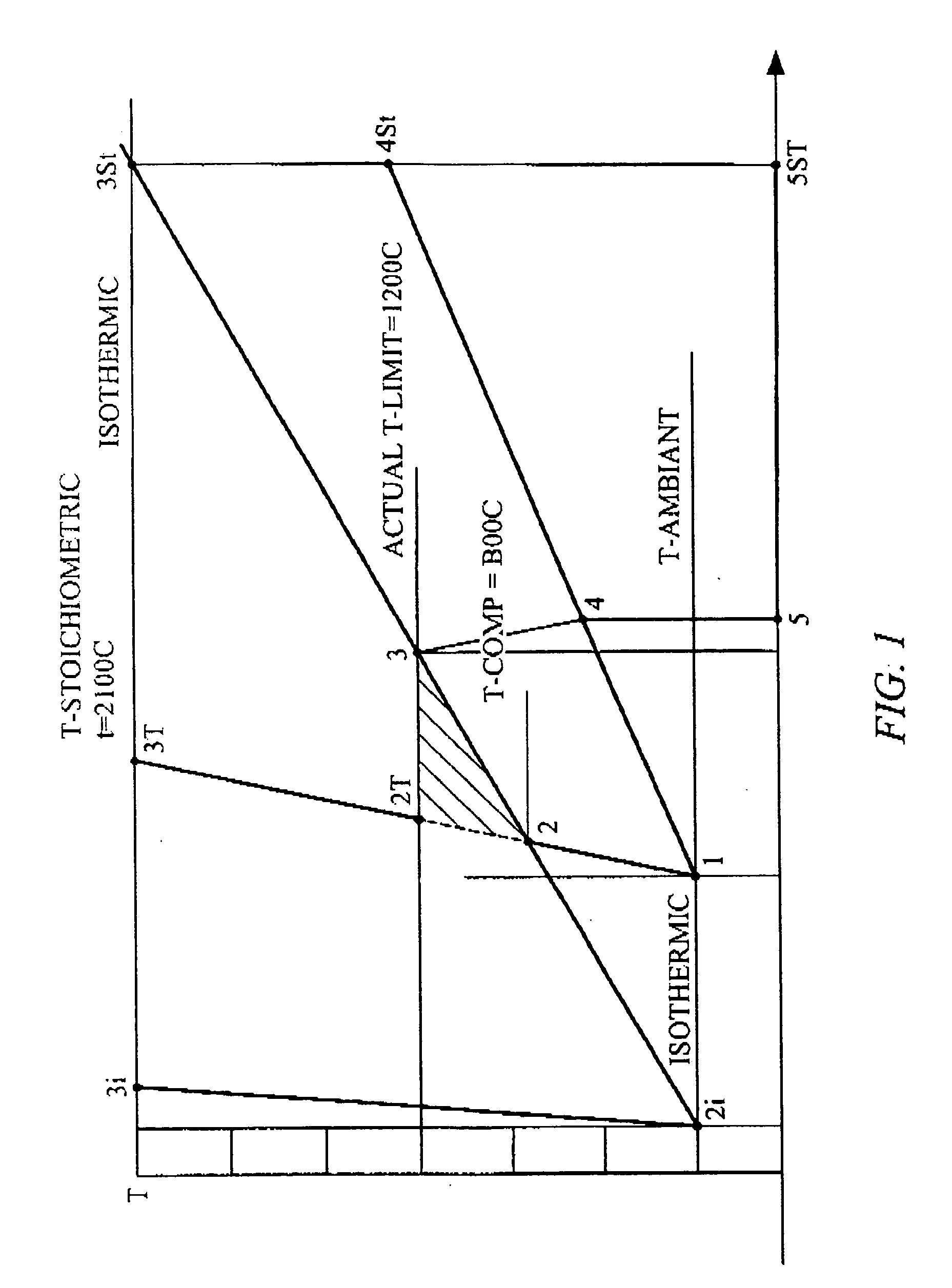
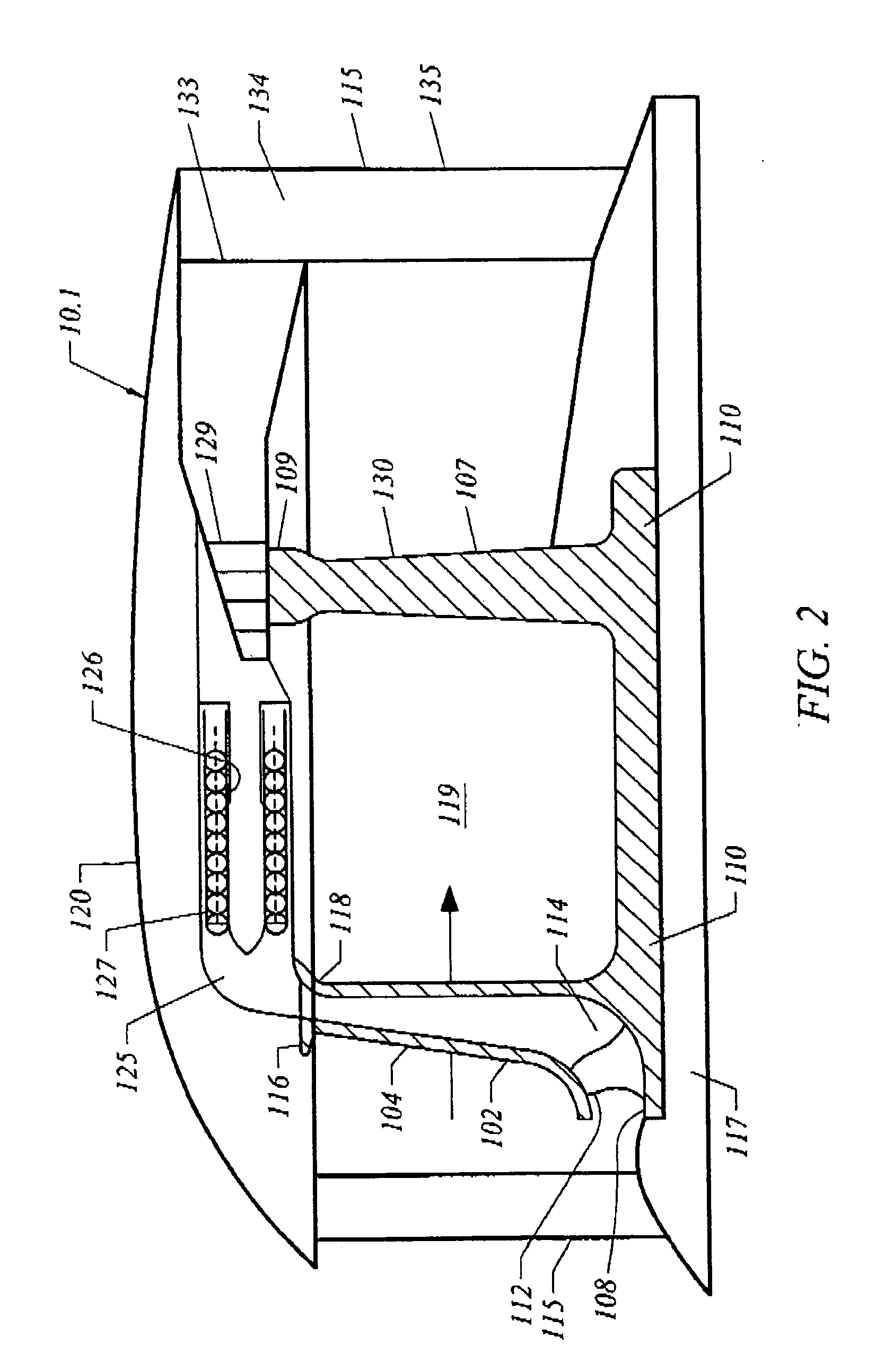
[0028] The universal Carnot cycle engine of this invention is generally designated by the reference numeral 10. The preferred engine design of this description utilizes a novel isothermal compressor system as described in my referenced application to enable a maximized thermal difference between the compressed air available for thermal heating and the practical temperature limit for combustion as defined by the structural integrity of the turbine blades or blade segments subject to the high temperature of the motive gases after heating. Since the engine 10 of this invention is designed for high altitude flight, the entry temperature of air for compression is low, in the minus range of −50° C. to −100° C., and can be used for isothermal compression of the air not passed through the core of the engine as bypass air. With a maximized delta T or temperature difference available for thermal heating and expansion of the drive gases, multiple thermal sources can be considered in alternativ...


PUM


Abstract

Turbofan jet engines utilizing the Carnot cycle for improved performance with isothermal compression of combustion air and, in part, isothermal expansion of thermally heated air, the engines having a turbofan compressor rotor with hollow fan blades in a core bypass passage through the engine and an annular, peripheral thermal chamber with staged turbine blades in an expansion chamber where heated gases are supplied to multiple stages to maintain peak temperatures.

Description

REFERENCES TO PRIOR APPLICATIONS [0001] This application relies on the priority of the following provisional applications: [0002] U.S. Provisional Application Ser. No. 60 / 621,183, filed Oct. 21, 2004, entitled UNIVERSAL PROPULSION CARNOT CYCLES TURBO ROCKETRY; and [0003] U.S. Provisional Application Ser. No. 60 / 646,009, filed Jan. 21, 2005, entitled UNIVERSAL PROPULSION CARNOT CYCLES IN TURBO ROCKETRY.BACKGROUND OF THE INVENTION [0004] This invention utilizes a Carnot cycle to improve the performance of aircraft engines and is designed to utilize alternate thermal sources including fuel cells, nuclear power reactors and mixed fuel combustors for combined jet and rocket propulsion permitting extended and indefinite flight of manned and unmanned aircraft. [0005] Actual state-of-the-art conventional aerospace propulsion systems are under many limitations. Reduced gas turbine power density, reduced thrust to weight ratios, reduced thermal efficiency and reduced cycle pressure ratios are...

Claims


Application Information

Patent Timeline
Patent Type & Authority Applications(United States)
IPC IPC(8): F02K3/02
CPCF02C3/045F02C3/073F02C3/14F02C7/08F02C7/10F02K3/02F02K3/06F02K3/08Y02T50/671F05D2220/36F05D2210/42F05D2220/327Y02T50/60
Inventor PAUL, MARIUS A.
Owner PAUL MARIUS A
Why Eureka
Try Eureka