Galvanic element and method for the production thereof

a technology of galvanic elements and anodes, which is applied in the direction of secondary cells, battery service/maintenance, sustainable manufacturing/processing, etc., can solve the problems of graphite anodes, graphite anodes to burst or even ignite, and excess cell pressure, etc., to achieve high capacitance, high energy density, and high capacitance

Inactive Publication Date: 2017-02-23
ROBERT BOSCH GMBH
View PDF6 Cites 42 Cited by
  • Summary
  • Abstract
  • Description
  • Claims
  • Application Information

AI Technical Summary

Benefits of technology

[0033]Through the method according to the present invention, a galvanic element can be produced having high capacitance and large energy density. The high capacitance is achieved through the use of a metallic lithium anode. This high energy density of the anode is advantageously combined with an ion-conducting separator, so that liquid electrolyte can be done without. In preferred specific embodiments, the use of lithium garnet as ion-conducting separator is proposed, which ensures a particularly high ion conductivity, and thus also ensures, in addition to the high energy density, a high performance of the galvanic element. The produced separator has a residual porosity of less than 5%, no through-going porosity being present, and the separator thus being completely tight.
[0034]Advantageously, according to the method of the present invention, despite the use of an anode based on metallic lithium it is not necessary to handle metallic lithium during the production. In the production of the galvanic element, the lithium is introduced in the form of a lithiated cathode active material, which is stable and easier to handle in comparison with metallic lithium.

Problems solved by technology

A disadvantage of lithium-ion cells having liquid electrolyte is that under mechanical and thermal stress the liquid electrolyte components can decompose, resulting in excess pressure in the cell.
Without corresponding protective measures, this can cause the cell to burst or even to ignite.
A disadvantage of the use of a graphite anode is its comparatively low energy density compared to an anode based on lithium metal.
Lithium metal-based anodes in turn are difficult to handle during the production of a galvanic element, because lithium has a high reactivity and is stable only in completely dry environments.

Method used


Image

  • Galvanic element and method for the production thereof
  • Galvanic element and method for the production thereof

Examples


Embodiment Construction

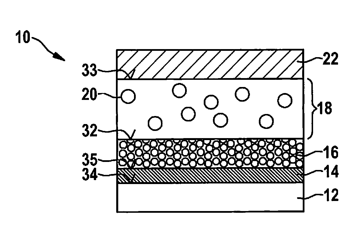
[0037]FIG. 1 shows a galvanic element 10. In the situation shown in FIG. 1, step a) of the method is carried out. Here, steps i) through iv) are run through in order to produce the layer sequence. First, in step i) a current conductor 12 assigned to the anode is provided. This is realized for example as copper foil. In the second step ii), a separator 16 is applied on current conductor 12 assigned to the anode, a first boundary layer 31 forming between current conductor 12 assigned to the anode and separator 16. As initial product for separator 16, a ceramic powder is suitable, applied for example by aerosol coating onto current conductor 12 assigned to the anode. As ceramic powder, in particular lithium garnet is suitable, which has good conductivity for lithium ions. Separator 16 is not electrically conductive, so that it also assumes the function of an electrical insulator.

[0038]In the third step iii), a cathode 18 is applied onto separator 16, so that a second boundary layer 32 ...


PUM

PropertyMeasurementUnit
particle sizeaaaaaaaaaa
thicknessesaaaaaaaaaa

Abstract

A method for producing a galvanic element that includes the following steps: a) production of a layer sequence including, in this order, a current conductor assigned to an anode, an ion-conducting and electrically insulating separator, a cathode having lithium-containing cathode material, and a current conductor assigned to the cathode, and b) charging of the galvanic element, an anode including metallic lithium forming between the current conductor assigned to the anode and the separator during charging of the galvanic element. In addition, a battery cell including such a galvanic element, and a battery including a plurality of such battery cells, are also described.

Description

FIELD[0001]The present invention relates to a galvanic element and to a method for producing such a galvanic element, the galvanic element including a current conductor assigned to the anode, an anode, a separator, a cathode, and a current conductor assigned to the cathode. In addition, the present invention relates to a battery cell including such a galvanic element, and to a battery including a plurality of such battery cells.BACKGROUND INFORMATION[0002]Lithium-ion batteries are distinguished, inter alia, by a very high specific energy and an extremely low self-discharge. Lithium-ion cells have at least one positive electrode and at least one negative electrode (cathode or, respectively anode), and during the charging and discharging of the battery lithium ions migrate from one electrode to the other electrode. For the transport of the lithium ions, a so-called lithium-ion conductor is necessary. In lithium-ion cells currently used, for example in consumer electronics (mobile tele...

Claims


Application Information

Patent Timeline
Patent Type & Authority Applications(United States)
IPC IPC(8): H01M4/04H01M10/44H01M4/36H01M10/0525H01M10/0565H01M4/62H01M4/38H01M4/131
CPCH01M4/0447H01M4/382H01M10/446H01M4/131H01M10/0525H01M2300/0082H01M4/625H01M4/364H01M2004/027H01M2220/30H01M10/0565H01M4/1395H01M10/052H01M10/0562H01M2300/0071Y02P70/50Y02E60/10Y02T10/70
Inventor KERKAMM, INGO
Owner ROBERT BOSCH GMBH
Why Eureka
Try Eureka