Radio-wave transparent cover and method for manufacturing radio-wave transparent cover

a technology of radio wave and transparent cover, applied in the field of radio wave transparent cover, to achieve the effect of shortening the tim

Inactive Publication Date: 2015-05-21
TOYODA GOSEI CO LTD
View PDF2 Cites 29 Cited by
  • Summary
  • Abstract
  • Description
  • Claims
  • Application Information

AI Technical Summary

Benefits of technology

[0012]According to this method, the suppression member, which is molded in advance, is arranged on the rear surface of the decorative layer to cover the rear surface of the decorative layer. Accordingly, when the base is insert-molded on the rear surface of the transparent member, heat transfer from the second resin material in a heated molten state to the transparent member is suppressed. The decorative layer and the transparent member are thus protected. As

Problems solved by technology

As a result, thermal damage such as whitening is

Method used


Image

  • Radio-wave transparent cover and method for manufacturing radio-wave transparent cover
  • Radio-wave transparent cover and method for manufacturing radio-wave transparent cover
  • Radio-wave transparent cover and method for manufacturing radio-wave transparent cover

Examples


Embodiment Construction

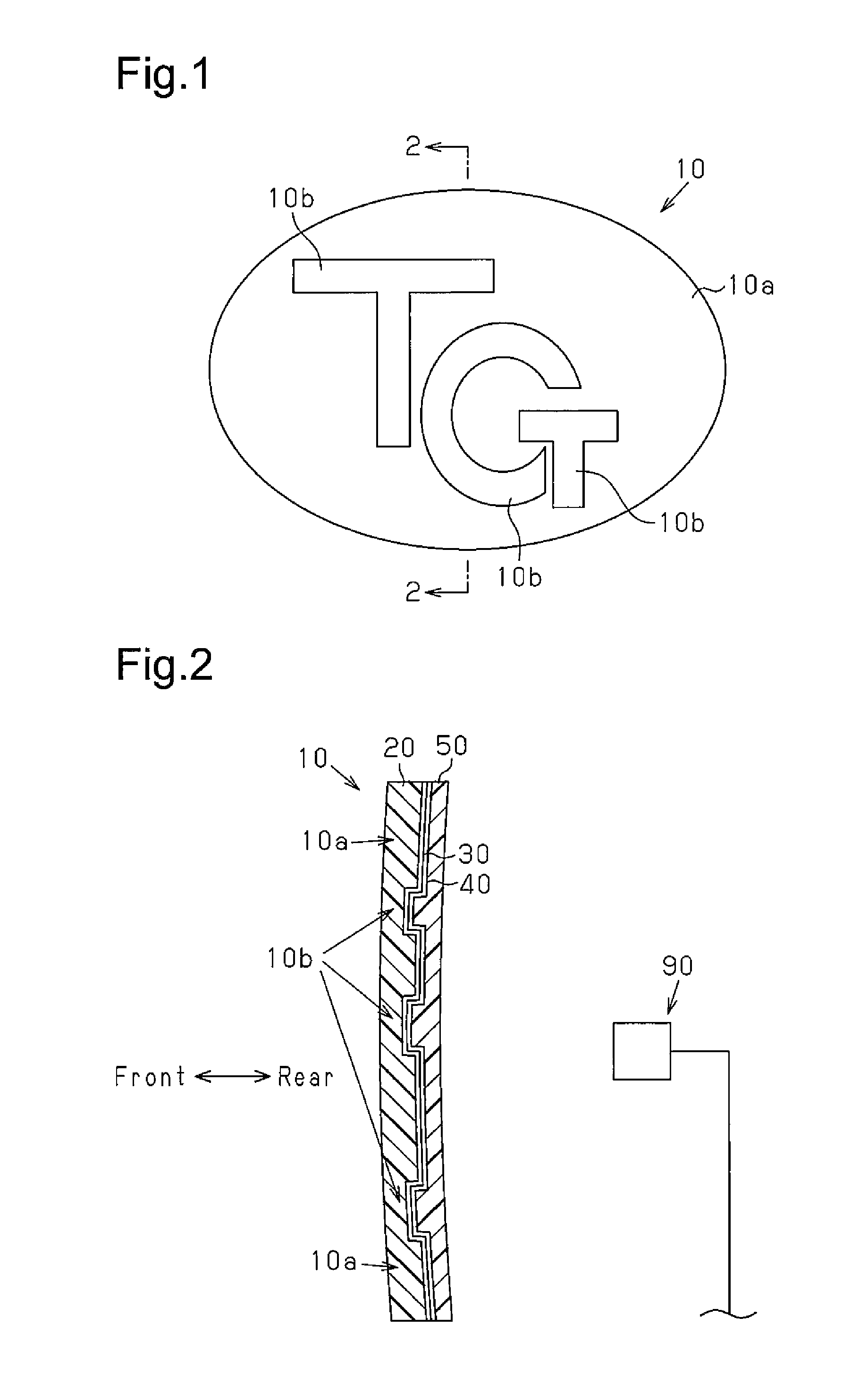
[0020]With reference to FIGS. 1 to 5C, a radio-wave transparent cover and a method for manufacturing the radio-wave transparent cover according to one embodiment will now be described. In the drawings, the components are represented in different scales so that they are recognizable, when necessary.

[0021]As illustrated in FIGS. 1 and 2, a radio-wave transparent cover (hereinafter, abbreviated as a cover 10) is an emblem attached to an opening of a front grille, which is arranged on a front surface of a vehicle. The cover 10 is located at the front side of a radar device 90 and arranged on a radio wave path of the radar device 90.

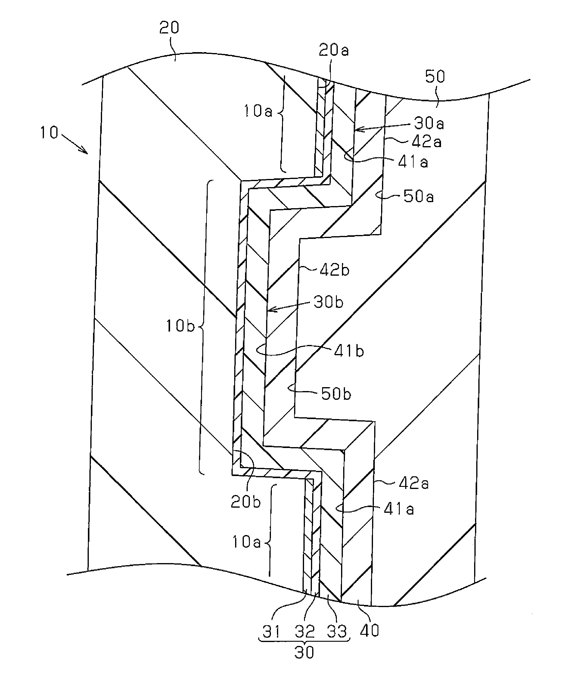
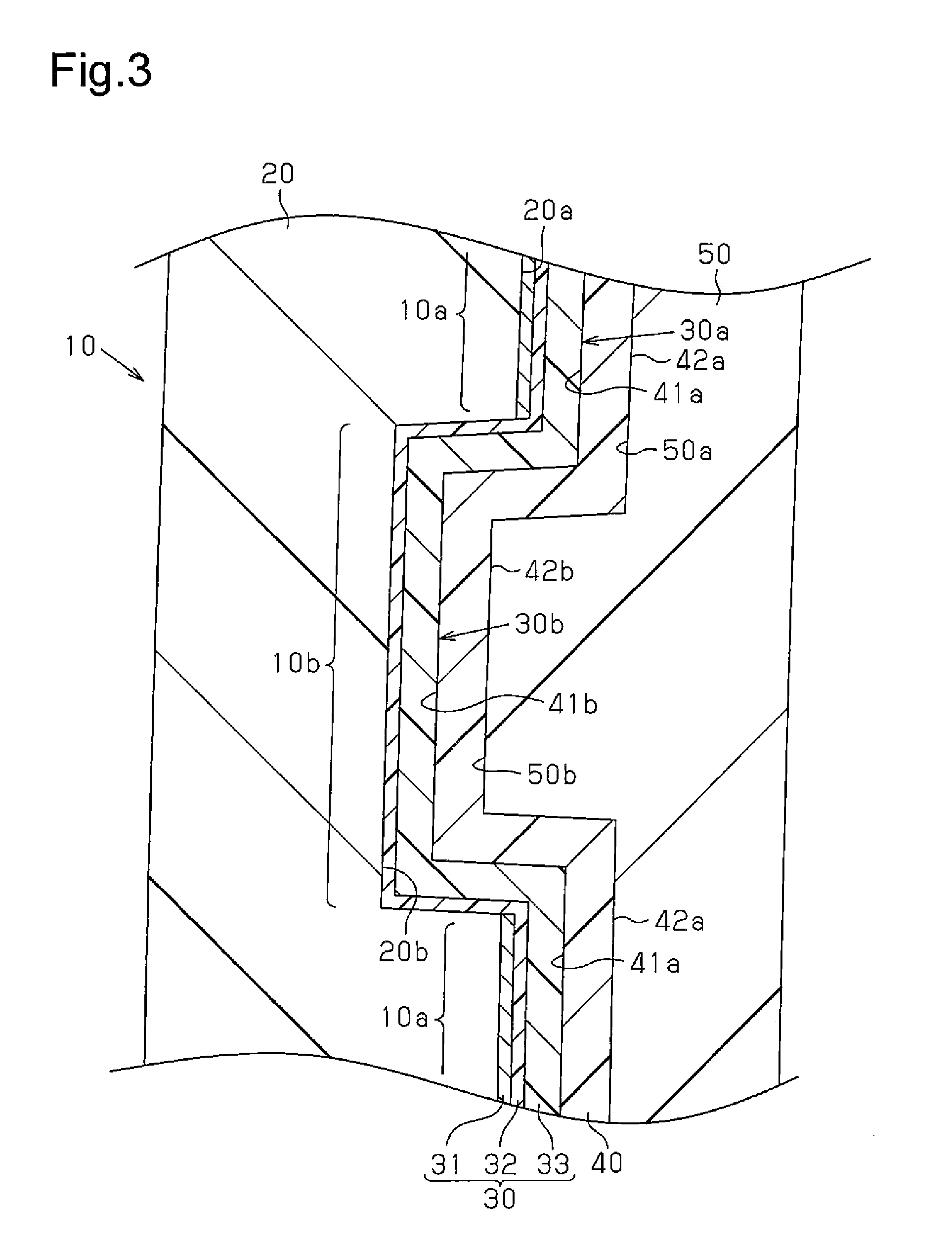
[0022]With reference to FIG. 2, the cover 10 has a transparent member 20 formed of an acrylic resin, which is an example of a first resin material. The transparent member 20 is formed of a polymethyl-methacrylate resin (PMMA resin), which exhibits particularly improved anti-wear performance. Referring to FIG. 3, the rear surface of the transparent member 20 i...


PUM

PropertyMeasurementUnit
Corrosion propertiesaaaaaaaaaa
Transparencyaaaaaaaaaa

Abstract

A radio-wave transparent cover is adapted to be arranged on a radio wave path of a radar device. The radio-wave transparent cover includes a transparent member, a decorative layer, a base, and a suppression member. The transparent member is formed of a first resin material. The decorative layer is formed on the rear surface of the transparent member. The base is formed of a second resin material and arranged behind the decorative layer. The suppression member is formed of a third resin material and molded in advance. The suppression member is arranged on the decorative layer to cover the rear surface of the decorative layer. The suppression member suppresses heat transfer to the transparent member when the base is insert-molded.

Description

BACKGROUND OF THE INVENTION[0001]The present invention relates to a radio-wave transparent cover arranged on a radio wave path of a radar device and a method for manufacturing the radio-wave transparent cover.[0002]Some recent vehicles employ a millimeter wave radar device to measure the distance and relative speed between the vehicles and nearby obstacles. The millimeter wave radar device is arranged behind a radiator grille or an emblem, which is provided in the front surface of a vehicle.[0003]In many cases, radiator grilles and emblems include shiny metal surfaces formed through chromium plating to provide a quality appearance. However, a shiny metal surface hampers radio wave transmission, thus making it impossible to arrange a radiator grille or an emblem having the shiny metal surface at the front side of a millimeter wave radar device.[0004]To solve this problem, it has been proposed to form an opening in a portion of a radiator grille located at the front side of a millimet...

Claims


Application Information

Patent Timeline
IPC IPC(8): B29C45/00B60R13/00B32B3/08B32B3/30B32B27/08
CPCB29C45/0003B32B3/30B32B27/08B32B3/08B60R13/005B29K2077/00B32B2307/304B32B2451/00B32B2307/752B29K2033/08B29K2025/08B32B2307/412B32B27/302B32B27/34B29L2031/3456B29K2995/0027B29C45/14836B29C45/1671B29C45/006B29C2045/14844B29C2045/1673Y10T428/234Y10T428/24521Y10T428/24529Y10T428/31757G01S2013/93271G01S7/027
Inventor SUGIURA, TATSUYAMAEDA, HIDETOKAWASHIMA, DAIICHIRO
Owner TOYODA GOSEI CO LTD
Why Eureka
Try Eureka