Pin spacers for connector assemblies

a technology of connector assemblies and spacers, which is applied in the direction of coupling device connections, electrical devices, coupling protective earth/shielding arrangements, etc., can solve the problems of pins being susceptible to damage and pins to bend

Active Publication Date: 2015-05-21
TYCO ELECTRONICS LOGISTICS AG (CH)
View PDF6 Cites 8 Cited by
  • Summary
  • Abstract
  • Description
  • Claims
  • Application Information

AI Technical Summary

Benefits of technology

[0008]Optionally, the lugs may block a pin spacer of an adjacent connector assembly from entering the space. The lugs may block lateral shifting of the pin spacer relative to a pin spacer of an adjacent connector assembly.

Problems solved by technology

When the electrical connectors shift, the pins are susceptible to damage, such as bending.
For example, the pin spacer of one receptacle connector may overlap with the pin spacer of an adjacent electrical connector, causing the pins to bend.

Method used


Image

  • Pin spacers for connector assemblies
  • Pin spacers for connector assemblies
  • Pin spacers for connector assemblies

Examples


Embodiment Construction

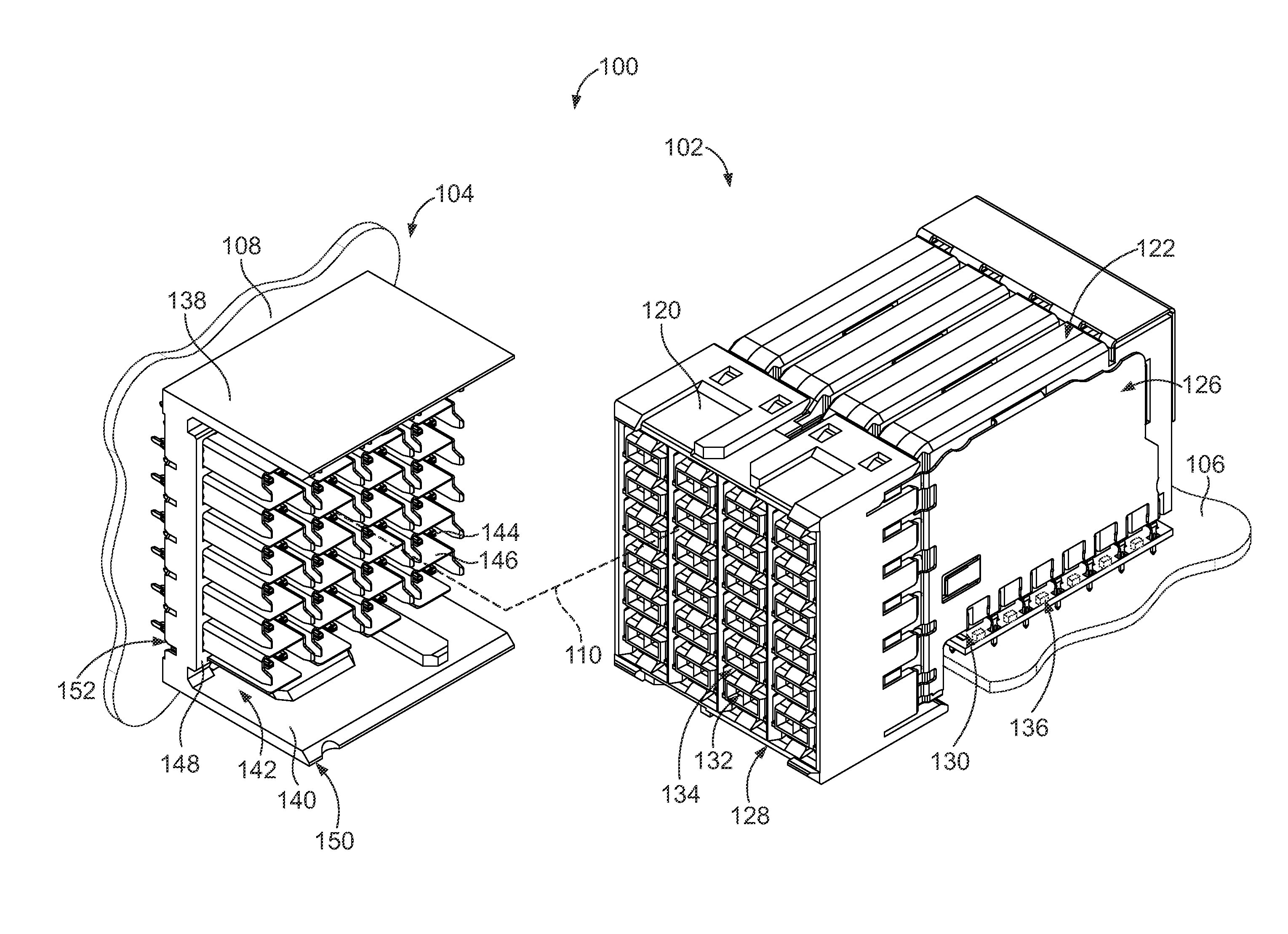
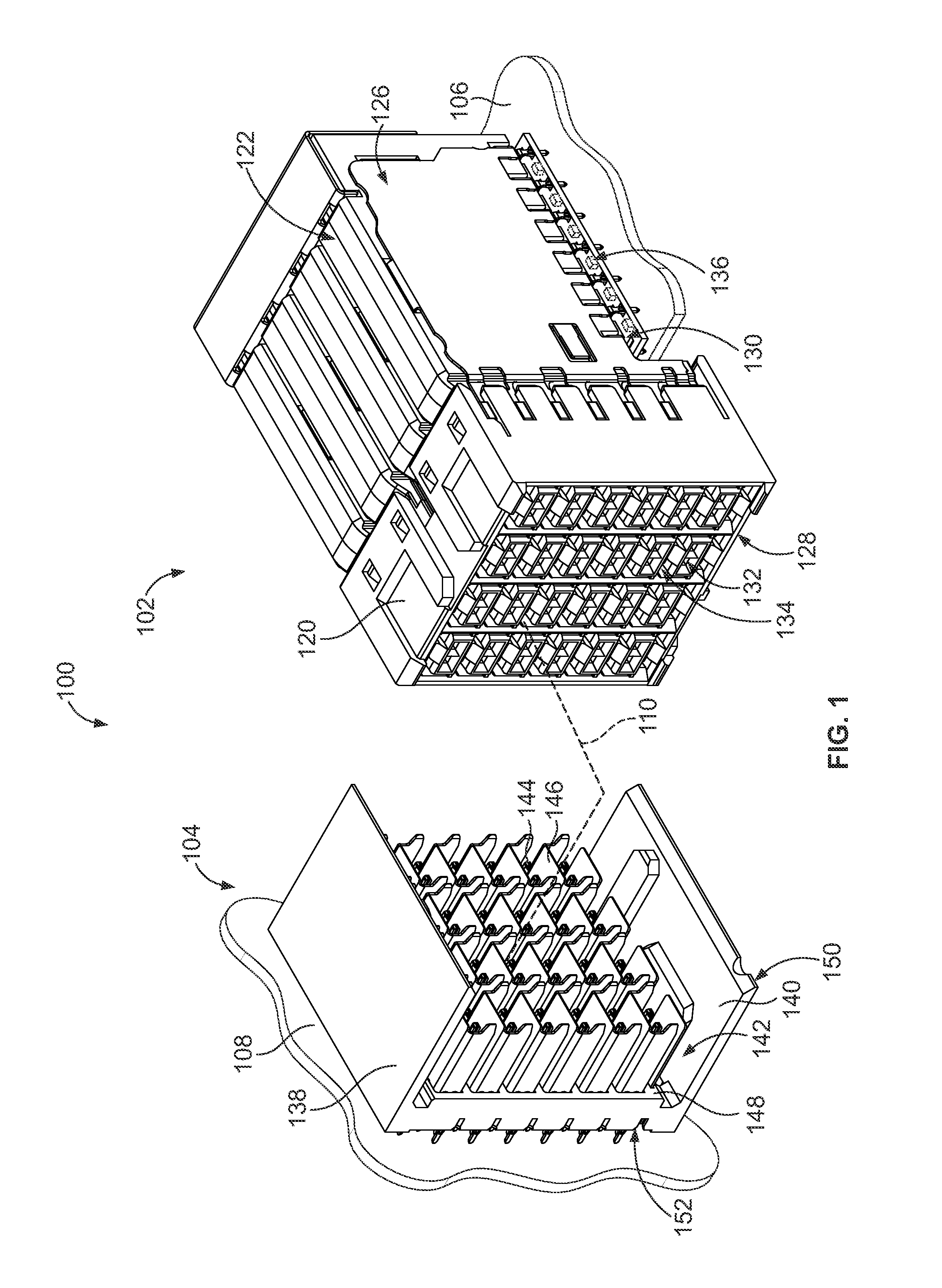
[0024]FIG. 1 is a perspective view of an electrical connector system 100 formed in accordance with an exemplary embodiment. The connector system 100 includes first and second connector assemblies 102, 104. In the illustrated embodiment, the first connector assembly 102 is a receptacle assembly and may be referred to hereinafter as a receptacle assembly 102 and the second connector assembly 104 is a header assembly and may be referred to hereinafter as a header assembly 104. Other types of connector assemblies may be used in alternative embodiments, such as a vertical connector, a right angle connector or another type of connector. The subject matter described herein provides a pin spacer for any type of connector assembly, such as the receptacle assembly 102, the header assembly 104 or other types of connector assemblies.

[0025]The receptacle and header assemblies 102, 104 are each electrically connected to respective circuit boards 106, 108. The receptacle and header assemblies 102,...


PUM


Abstract

A connector assembly includes a housing, a plurality of contact modules received in the housing, and a pin spacer coupled to the contact modules. Each contact module has a plurality of contacts each including a pin extending from a bottom of the corresponding contact module. The pin spacer has a plurality of pin holes extending through the pin spacer. The pin holes receive corresponding pins for mounting to the circuit board. The pin spacer holds relative positions of the pins. The pin spacer has side edges at opposite sides of the pin spacer and lugs extending from the top of the pin spacer proximate to the sides of the pin spacer. The lugs block entry into a space defined between the bottoms of the contact modules and the top of the pin spacer.

Description

BACKGROUND OF THE INVENTION[0001]The subject matter herein relates generally to pin spacers for connector assemblies.[0002]Some electrical systems utilize electrical connectors, such as header assemblies and receptacle assemblies, to interconnect two circuit boards, such as a motherboard and daughtercard. The electrical connectors include contacts having pins extending from a mounting end of the electrical connectors. The pins are through-hole mounted to the circuit board by loading the pins into plated vias in the circuit board. The electrical connectors are typically pre-assembled and configured to be mounted to the circuit board. In order to insure that the pins are oriented correctly, many electrical connectors include pin spacers or pin organizers that are coupled to the bottoms of the electrical connectors and that hold the pins in proper positions for mounting to the circuit board.[0003]The electrical connectors are typically shipped with the pin spacers in an intermediate po...

Claims


Application Information

Patent Timeline
Patent Type & Authority Applications(United States)
IPC IPC(8): H01R9/24H01R13/6596
CPCH01R13/6596H01R9/2408H01R12/724H01R13/6397
Inventor WICKES, EVAN CHARLESDAVIS, WAYNE SAMUALANNIS, KYLE GARY
Owner TYCO ELECTRONICS LOGISTICS AG (CH)
Why Eureka
Try Eureka