Cabin for a floating installation with lines which contribute to reinforcement

a technology of floating installation and cabin, which is applied in the field of cabins for floating installations, can solve the problem that the region is only accessible with difficulty, and achieve the effects of low thermal conductivity, high imperviousness, and adequate strength

Active Publication Date: 2015-05-28
DR ING H C F PORSCHE AG
View PDF2 Cites 5 Cited by
  • Summary
  • Abstract
  • Description
  • Claims
  • Application Information

AI Technical Summary

Benefits of technology

[0007]According to the invention, the conduits are supply conduits which can supply different media to the cabin. For example, the supply conduits can supply air, water, data, electricity, lighting etc. to the cabin. According to the invention, the conduits are integrated in the room unit such that said conduits simultaneously perform a stiffening function for the room unit. Here, it may be expedient for the conduits to be arranged along the length extent and / or the width extent and / or the height extent of the room unit, which contributes considerably to increasing the basic rigidity of the cabin.
[0021]The cabins may advantageously be arranged one on top of the other and / or adjacent to one another within the ship. Owing to the conduits according to the invention, which serve to stiffen each cabin, the cabins according to the invention can be arranged one on top of the other. Here, the floor of the upper cabin may simultaneously be the ceiling of the lower cabin. A reduction of the structural height of the ship can be achieved in this way. It is likewise possible for additional ship decks to be realized. Furthermore, the weight of the ship can be reduced considerably, because fewer metallic frame profiles, which jointly define the floor region of each ship deck, are required.

Problems solved by technology

The arrangement of the supply conduits on the outer side of the room unit has the major disadvantage that said region is only accessible with difficulty, in particular because only little structural space is available for the technician in said region.

Method used


Image

  • Cabin for a floating installation with lines which contribute to reinforcement
  • Cabin for a floating installation with lines which contribute to reinforcement
  • Cabin for a floating installation with lines which contribute to reinforcement

Examples


Embodiment Construction

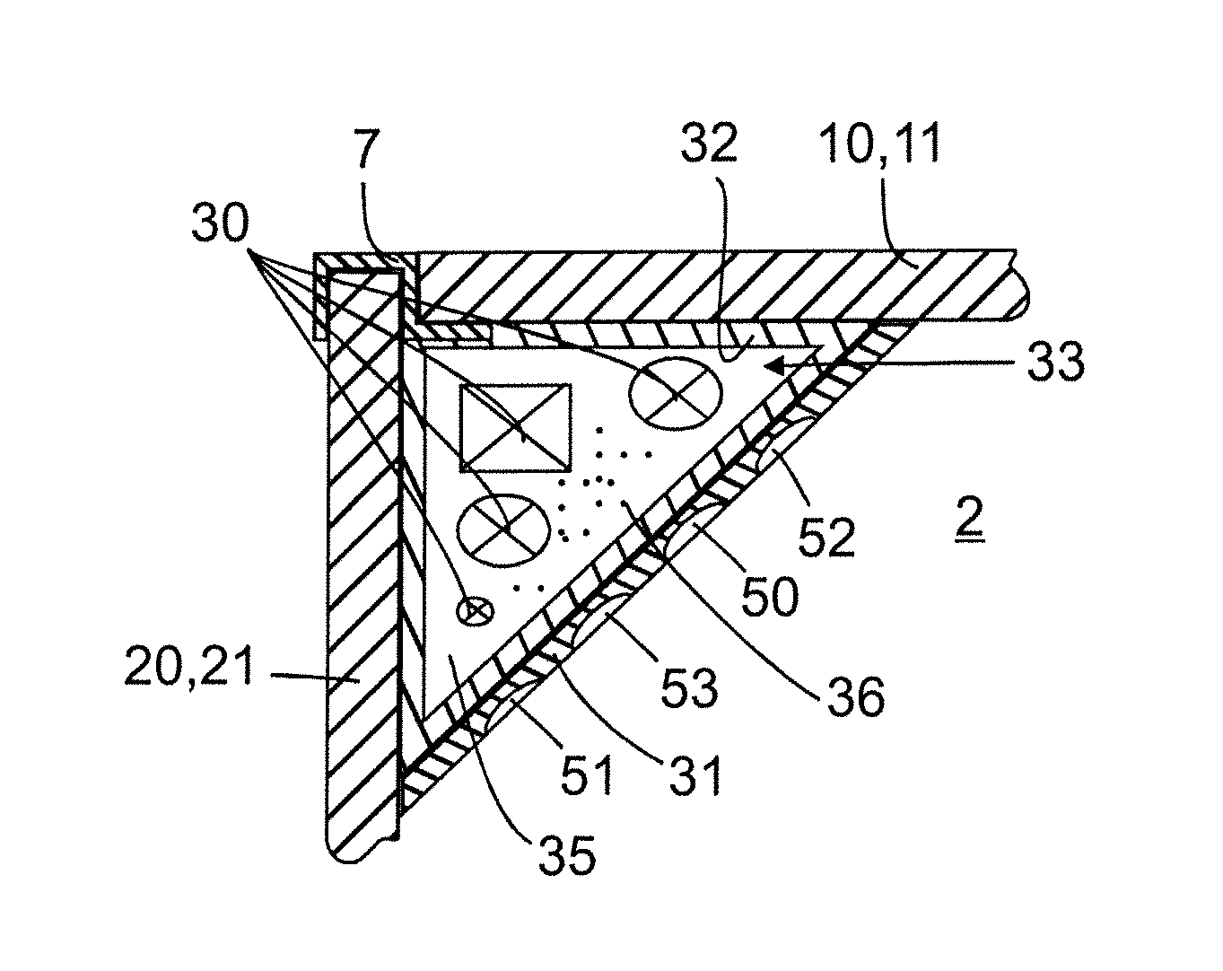
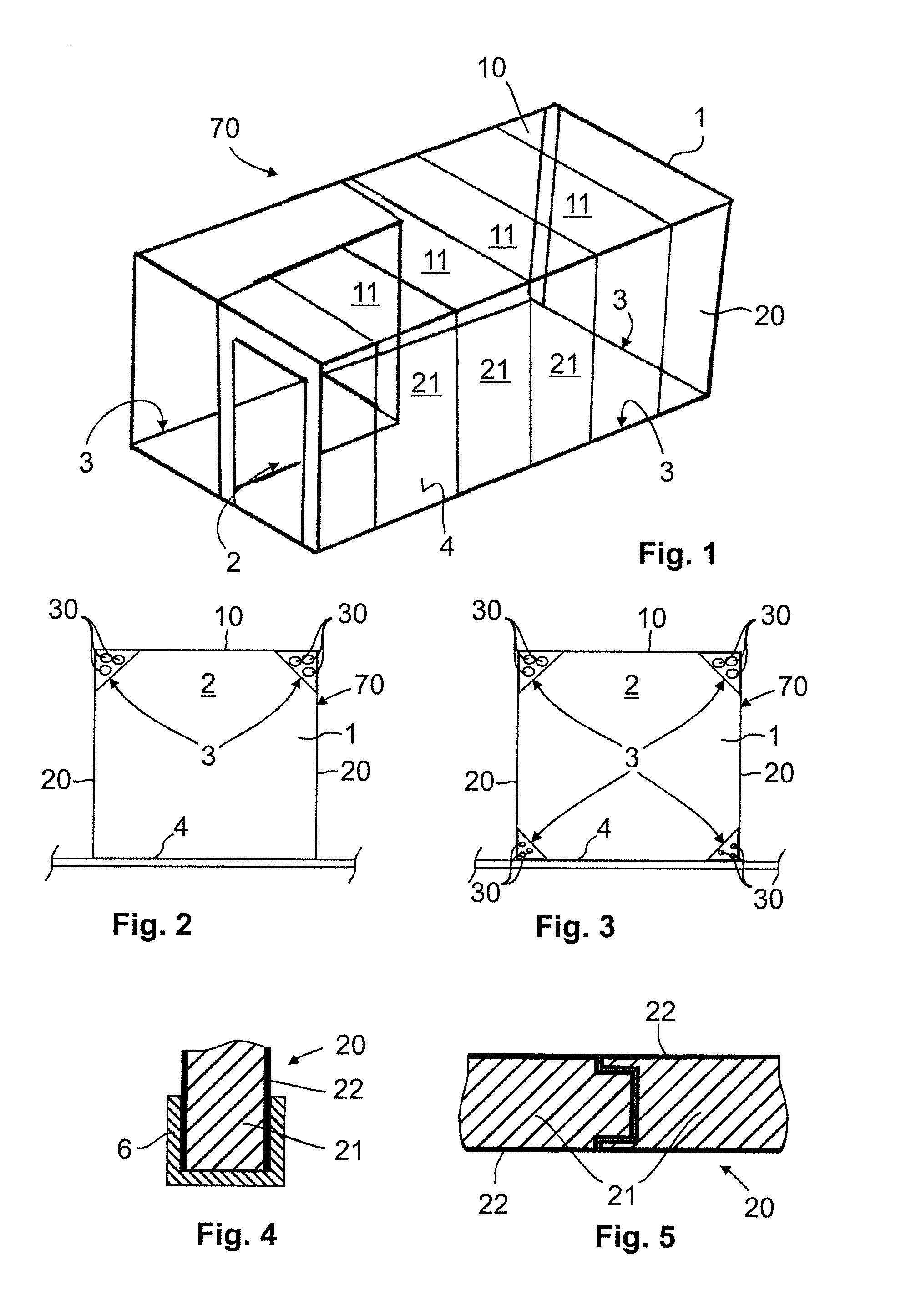
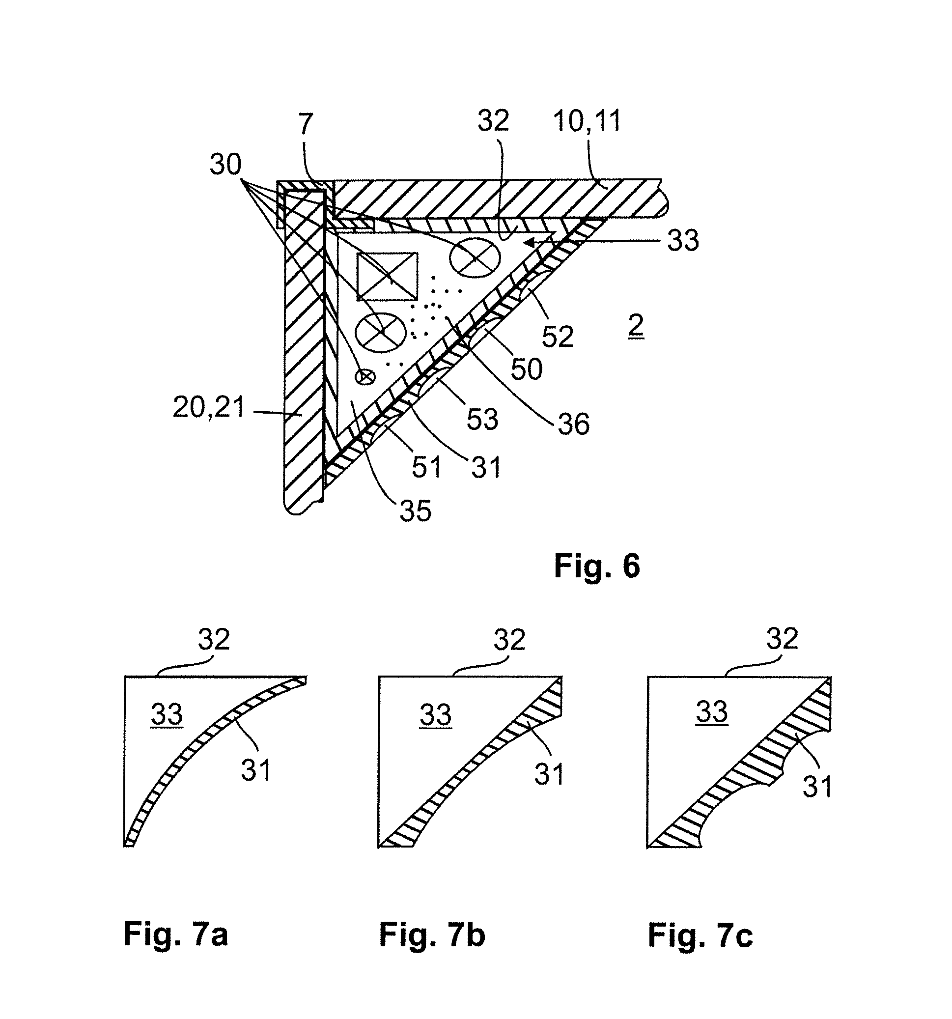
[0035]FIG. 1 shows a cabin 70 that can be installed in a ship 60 as per FIG. 9. As can be seen in FIG. 9, the ship 60 has a multiplicity of cabins 70 which are situated on different levels (decks). Each cabin 70 is equipped with supply conduits 30 such that electricity, lighting and air (by way of an air-conditioning system), for example, are available to each passenger in the cabin 70. It is likewise conceivable for waste water to be able to be discharged from the cabin 70 via the supply conduits 30. The passenger can likewise receive audible information via the supply conduits 30. It is furthermore possible for the user in the cabin 70 to be provided, via the conduits 30, with a network connection in order that they can receive and / or exchange electronic data. It is thus possible for any form of information technology to likewise be integrated into the conduits 30.

[0036]As shown in FIG. 1, the cabin constitutes a room unit 1 which is composed of a ceiling 10 and multiple walls 20....


PUM


Abstract

The invention relates to a cabin (70) for a floating installation, in particular for a ship (60), having a room unit (1) which is bounded at least by a ceiling (10) and walls (20), and lines (30) which supply the room unit (1), in particular with air, water, data, power, illumination, etc. Provision is made according to the invention for the lines (30) to extend in the room unit (1) in such a way that the lines (30) simultaneously act as reinforcing means for the room unit (1).

Description

BACKGROUND[0001]1. Field of the Invention[0002]The invention relates to a cabin for a floating installation, in particular for a ship, having a room unit, which is delimited at least by a ceiling and by walls, and conduits, which serve for providing a supply, in particular of air, water, data, electricity, lighting, etc., to the room unit.[0003]2. Description of the Related Art[0004]DE 198 28 505 A1 discloses a ship cabin which is composed of a load-bearing floor, a ceiling and wall elements. The floor is formed from a multiplicity of layers which exhibit different flexural strength and elasticity, whereby the cabin has improved characteristics with regard to its strength and basic rigidity. This is of great importance in particular during the transportation of the cabin and during the installation of the cabin on the ship. Consequently, transportation damage can be avoided owing to the increased stiffening of the cabin as a result of the use of the above-mentioned floor. It has dis...

Claims


Application Information

Patent Timeline
Patent Type & Authority Applications(United States)
IPC IPC(8): B63B29/02B63B11/00
CPCB63B11/00B63B29/02B63B29/025B63B45/06B63J2/04B63B2231/02
Inventor KOESTNER, MATTHIAS
Owner DR ING H C F PORSCHE AG
Why Eureka
Try Eureka