Leak-resistant liquid applicator

a liquid applicator and leak-resistant technology, which is applied in the field of leak-resistant liquid applicators, can solve the problems of unintended discharge or leakage of stored liquid, -manufacture leakage, and create an overpressure condition within the liquid storage shell, and achieve the effect of partial resistan

Active Publication Date: 2015-05-28
DAB O MATIC HLDG
View PDF4 Cites 2 Cited by
  • Summary
  • Abstract
  • Description
  • Claims
  • Application Information

AI Technical Summary

Benefits of technology

[0009]It is accordingly a desideratum of the invention to provide an improved liquid dispensing applicator that exhibits particular resistance to unintended leakage of stored liquid during periods of nonuse and, in particular, during shipping and transport from the manufacturer to the ultimate end user, and which additionally provides the ability to release an overpressure condition within the liquid storage container or reservoir at the point of manufacture.

Problems solved by technology

Although a tighter or more leak resistant valve closure can be effected by utilizing a stronger spring, increases in the spring force also disadvantageously require more user-applied force to open the valve for each release of liquid and thus necessitate an unfortunate trade-off between user convenience and operational effectiveness.
A particular issue in avoiding unintended stored liquid releases and leakage in current liquid applicator and dispenser constructions arises during their shipping and transport—i.e., when the manufactured devices are shipped or otherwise transported to the retailer or ultimate end user.
It is virtually certain that, at one or multiple points during such transport, the liquid-filled devices will be, at the very least, dropped, jostled and inverted, often resulting in unintended discharges or leakage of the stored liquid as the spring-based valving arrangement closure is unintendedly displaced.
Another cause of post-manufacture leakage arises due to the characteristics of some liquids commonly stored for dispensing from such devices.
Attachment (and liquid-tight securement) of the liquid-containing shell to the dispensing assembly, in which the valving arrangement is closed under the return urgency of a spring, often creates an overpressure condition within the liquid storage shell.
With especially free-flowing, and volatile, liquids, the elevated pressure in the liquid storage reservoir will often result in releases of liquid through the closed valving arrangement, particularly during transport and most especially where, as is common, the devices are transported by air in low pressure or unpressurized cargo holds which still further increase the relative difference between the elevated pressure in the liquid storage container and the ambient atmosphere.

Method used


Image

  • Leak-resistant liquid applicator
  • Leak-resistant liquid applicator
  • Leak-resistant liquid applicator

Examples


Embodiment Construction

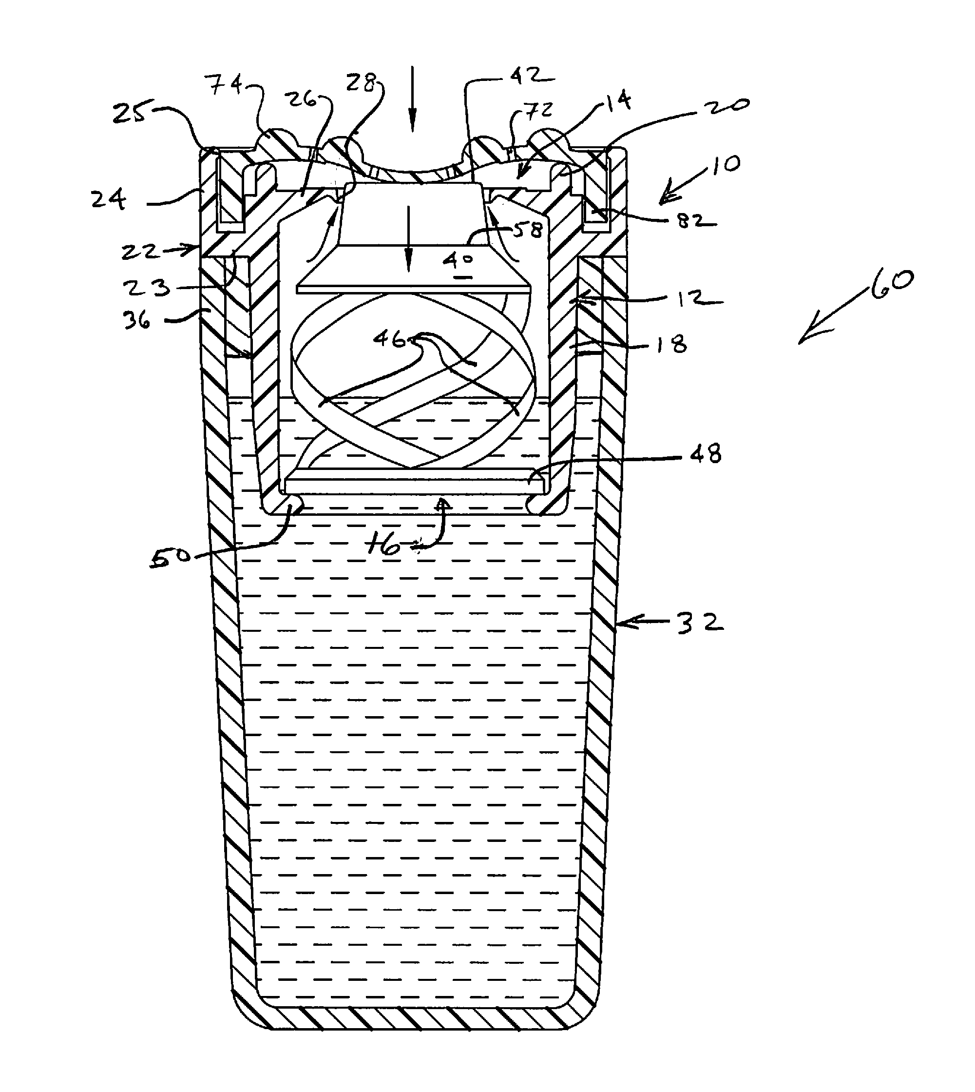
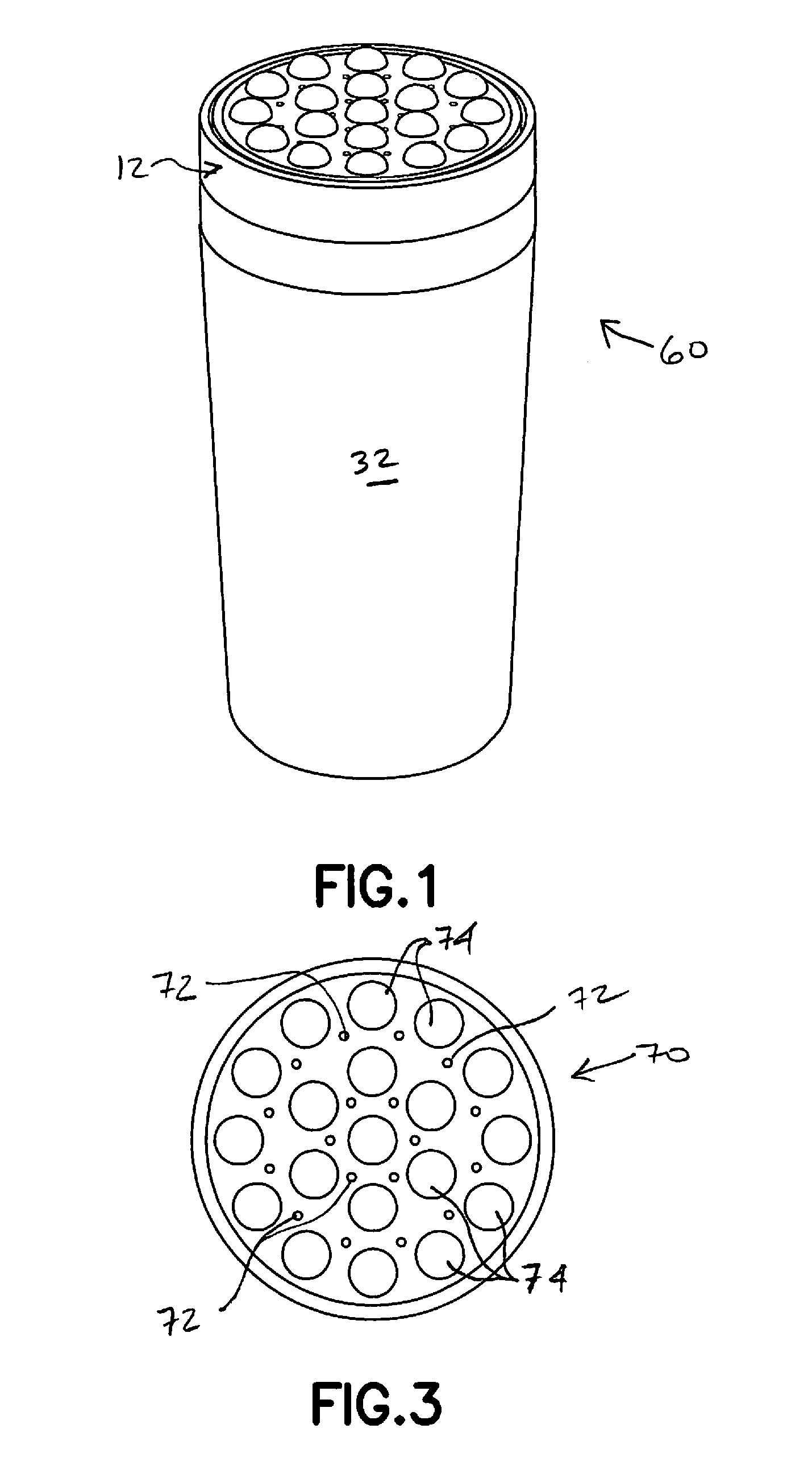
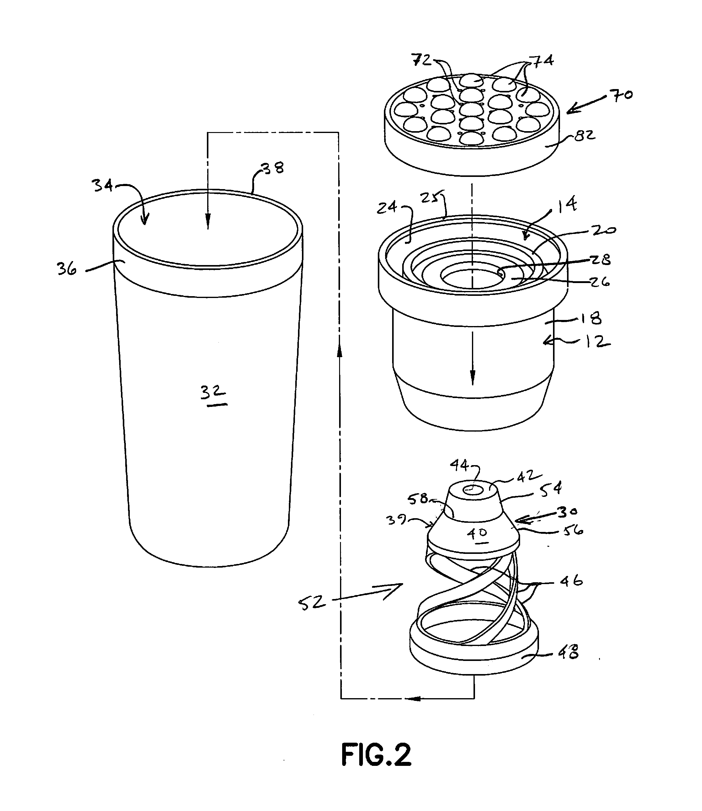
[0022]A preferred embodiment of a leak resistant (commonly referred to as leak-proof) liquid dispensing applicator 10 constructed in accordance with the present invention as depicted in the figures includes a housing 12 which extends axially between an open distal end that defines a liquid discharge opening 14 and an open proximal end that bounds a liquid intake or receiving opening 16. As used herein, the term “liquid” is intended to mean—and the inventive applicator is useful and can be readily configured to dispense—a flowable substance (that is neither solid nor gas) having a definite volume and no fixed shape, and having any of a wide range of viscosities, including by way of non-limiting example water (at one end of the spectrum) and creams (at the other). It is contemplated that the housing will generally be configured with a generally round or circular cross section, and the illustrated applicator embodiment 10 is so depicted and will be herein so described. Nevertheless, it...


PUM


Abstract

A stored liquid dispensing applicator includes a valving arrangement formed of a valve seat and a spring-driven shuttle that is disposed for axial displacement into and out of valve-defining abutment and engagement with the valve seat. The shuttle is displaceable between distal and proximal limits of travel that include a first position defining the distal limit and a second position proximally spaced from the distal limit and distally spaced from the proximal limit. The valve seat is arranged for contact with the shuttle uninterruptedly between the first and second positions to close the valve, and for spaced apart relation with the shuttle between the second position and the proximal limit of travel to open the valve for dispensing of stored liquid. The first position of the shuttle defines an enhanced second level seal, attainable only during manufacture of the device, that is especially resistant to unintended liquid flow or discharge between the valve seat and shuttle. The spring force distally driving the shuttle is sufficient to return the shuttle, from its proximal limit, only to the second position which defines a first level seal of the valving arrangement effective for preventing unintended releases of stored fluid during and between normal usages of the device.

Description

RELATED APPLICATION[0001]This application claims priority from U.S. Provisional Patent Application Ser. No. 61 / 909,130 which was filed on Nov. 26, 2013.BACKGROUND OF THE INVENTION[0002]1. Field of the Invention[0003]The present invention generally relates to the field of liquid dispensers or applicators and, more particularly, to user-operable applicators that are configured to selectively dispense a liquid—of virtually any viscosity, including creams—from a storage reservoir and which exhibit particular resistance to leakage or other unintended discharges of stored liquid during periods of non-use, including shipping and transport from the manufacturing site to an ultimate purchaser or end-user.[0004]2. Description of Related Art[0005]Liquid dispensers and dispensing applicators are ubiquitous in the market place of today, providing an inexpensive and easily used vehicle for supplying a wide range of liquid-based products to the public. A common feature of such dispensers and appli...

Claims


Application Information

Patent Timeline
Patent Type & Authority Applications(United States)
IPC IPC(8): B65D47/24B65D50/00
CPCB65D50/00B65D47/242A45D34/04B65D47/44
Inventor BELL, JAMESBELL, SCOTT
Owner DAB O MATIC HLDG
Why Eureka
Try Eureka