
Connection arrangement for an electrically conductive contact and a method for producing such a connection arrangement

a technology of electrically conductive contacts and connection arrangements, which is applied in the direction of ohmic-resistance heating, chemistry apparatus and processes, and other domestic objects, can solve the problems of affecting the mechanical strength of these adhesives, and hardly being able to produce electrically conductive connections that withstand high stress, so as to prevent damage to the screen

Active Publication Date: 2019-07-02
RICHARD FRITZ GMBH & CO KG
View PDF7 Cites 1 Cited by
  • Summary
  • Abstract
  • Description
  • Claims
  • Application Information

AI Technical Summary

Benefits of technology

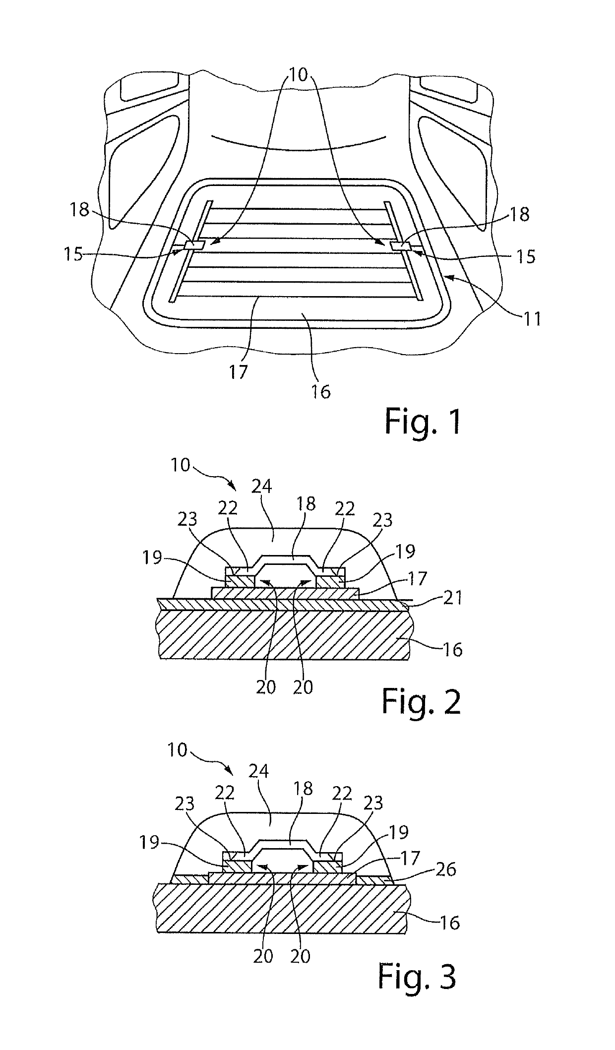
[0007]This object is solved by means of a connection arrangement for an electrically conductive contact between at least one electrical conductor provided on a screen, in particular for a motor vehicle, and an electrical coupling element in which at least one contact point between the coupling element and the electrical conductor is provided on a coupling point for the at least one electrical conductor and in which the electrical coupling element and the electrical conductor are connected to each other by means of an electrically conductive compound, and in which the at least one contact point of the coupling point is at least partially surrounded by a casting compound. By means of the casting compound that at least partially surrounds the contact point of the coupling point, a connection is created between the coupling element and the electrical conductor which withstands high mechanical stresses. Thus, this connection arrangement resists both strong peeling forces and high cyclical stresses and / or thermal influences such that the maintenance of the electrical contact is ensured.
[0008]An advantageous development of the connection arrangement provides that the at least one contact point is completely encased by the casting compound and the casting compound surrounding the at least one contact point touches the screen. As a result of the contact point being completely encased by the casting compound, a particularly strong and durable connection arrangement is formed. In addition, because the casting compound touches the screen, fixing the contact point on the screen is achieved. As a result, a highly resilient connection is formed both between the coupling element and the electrical conductor and between the coupling element and the screen. Here, the surface of the screen forms an adhesive surface for the casting compound.
[0010]It is particularly preferably provided that the casting compound forms an additional adhesive connection between the at least one coupling element and the screen. By forming this additional adhesive connection, fixing the coupling element on the screen is achieved. The casting compound here has a corresponding degree of elasticity, such that damage to the screen as a result of the adhesive connection, in particular as a result of curing the adhesive connection, is avoided.
[0012]In a further advantageous embodiment of the connection arrangement, it is provided that the casting compound is formed as a single-component or a two-component adhesive that preferably consists of polyurethane, silicone, acrylate, MS-polymer or epoxy resin. As a result of this embodiment of the casting compound, a high-strength adhesive is formed with which a highly resilient connection element can be produced. As a result, the electrical contact between the coupling element and the electrical conductor is ensured over a long period of time. In addition, the preferred materials offer particularly advantageous properties for processing the casting compound and, at the same time, form a particularly durable connection.
[0016]In a further embodiment of the connection arrangement, it is provided that the screen is formed as single-pane toughened glass (ESG) or as laminated glass (VSG). In particular, screens of a motor vehicle are often formed as single-pane toughened glass or as laminated glass, as well. These screens offer particular safety advantages in the event of damage, for example in the event of an accident, or offer particular resistance to break-ins.
[0017]Furthermore, the object underlying the invention is solved by a method for producing a connection arrangement between at least one electrical conductor provided on a screen, in particular for motor vehicles, and an electrical coupling element, in particular according to one of the embodiments described above, wherein the at least one coupling element on at least one contact point of a coupling point and the electrical conductor are connected to an electrically conductive compound and, subsequently, the at least one contact point formed is encased by a casting compound. As a result of this method, a connection between the coupling element and the electrical conductor is formed that is particularly resistant to external influences. In addition, by using the casting compound, damage to the screen is prevented. Thus, by means of this method, a connection arrangement is formed that withstands both strong peeling forces and high cyclic stresses, as well as being able to be formed to be gentle towards the screen and able to be manufactured in a cost-effective manner.

Problems solved by technology

However, because of EU guidelines, these lead-containing solders are not allowed to be used in this context as of 1 Jan. 2016 such that, in the future, only lead-free solder materials can be used.
However, existing lead-free solders have the disadvantage that, in particular with laminated glass (VSG), glass breakages and, with toughened glass (ESG), ceramic breakages often take place.
The electrically conductive adhesives used for this have a high proportion of conductive components, for example copper or silver, that, however, negatively influence the mechanical strength of these adhesives.
Electrically conductive connections that withstand high stress are hardly possible, or not at all possible, with such adhesives.

Method used


Image

  • Connection arrangement for an electrically conductive contact and a method for producing such a connection arrangement

Examples


Embodiment Construction

[0023]FIG. 1 shows a perspective view of a screen unit 11 of a motor vehicle. By way of example, this screen unit 11 is formed as a rear screen of the motor vehicle. This screen unit 11 can also be formed as a front screen, a side screen or as a screen for sealing a roof opening of the motor vehicle. The screen unit 11 is provided, in particular, as a fixed screen unit. At the same time, this can also be able to be opened. The screen unit 11 comprises a screen 16. This screen 16 is preferably formed from single-pane toughened glass (ESG) or from laminated glass (VSG). In addition, a ceramic coating 21 and / or a primer or adhesion promoter 26 can be applied on the screen 16.

[0024]The screen 16 has an electrical conductor 17. This electrical conductor 17 can form, for example, a screen heating device for heating the screen 16. At the same time, the electrical conductor 17 can be provided as an anti-theft device or an antenna for a car radio, car television, GPS or similar. The electric...


PUM

PropertyMeasurementUnit
electrically conductiveaaaaaaaaaa
adhesiveaaaaaaaaaa
adhesionaaaaaaaaaa

Abstract

The invention relates to a connection arrangement for an electrically conductive contact between at least one electrical conductor (17) provided on a screen (16), in particular for a motor vehicle, and an electrical coupling element (18), wherein at least one contact point (20) between the coupling element (18) and the electrical conductor (17) is provided on a coupling point (15) for the at least one electrical conductor (17) and wherein the electrical coupling element (18) and the electrical conductor (17) are connected to each other by means of an electrically conductive compound (19), and wherein the at least one contact point (20) of the coupling point (15) is at least partially surrounded by a casting compound (24), and a method for producing such a connection arrangement (10).

Description

CROSS-REFERENCE TO RELATED APPLICATIONS[0001]This application claims priority to German Patent Application DE 10 2016 112 566.0, titled: A connection arrangement for an electrically conductive contact and a method for producing such a connection arrangement, Filed on 8 Jul. 2016.STATEMENT REGARDING FEDERALLY SPONSORED RESEARCH OR DEVELOPMENT[0002]Not Applicable.BACKGROUND OF THE INVENTIONTechnical Field[0003]The invention relates to a connection arrangement for an electrically conductive contact and a method for producing such a connection arrangement.Related Background Art[0004]Connection arrangements for forming an electrically conductive contact between an electrical conductor and a coupling element are known, in which the coupling element is soldered to a soldering material on the electrical conductor. This electrical conductor can be formed, for example, as an antenna, an anti-theft device or a heating device in or on a screen for a motor vehicle. Soldering on a screen places s...

Claims


Application Information

Patent Timeline
Patent Type & Authority Patents(United States)
IPC IPC(8): H02G3/00B32B17/10H05B3/84B29D23/00
CPCH05B3/84B29D23/005B32B17/10036B32B17/1055B32B17/10376B32B17/10871H05B2203/016B29K2995/0005H05B2203/003H05B2203/011H05B2203/014
Inventor SCHOEN, MICHAEL
Owner RICHARD FRITZ GMBH & CO KG
Learn More