Hysteresis compensated force sensing device and method

Inactive Publication Date: 2018-08-30
TORQUE & MORE TAM
View PDF0 Cites 7 Cited by
  • Summary
  • Abstract
  • Description
  • Claims
  • Application Information

AI Technical Summary

Benefits of technology

[0040]It may be an aspect of the description to compensate a hysteresis effect of an object to be sensed, so that a gained signal representing the applied torque can be freed of a hysteresis related signal portion to arrive at

Problems solved by technology

It is the inability of the material to return back to its original state when an external force or magnetic field previously appli

Method used


Image

  • Hysteresis compensated force sensing device and method
  • Hysteresis compensated force sensing device and method
  • Hysteresis compensated force sensing device and method

Examples


Embodiment Construction

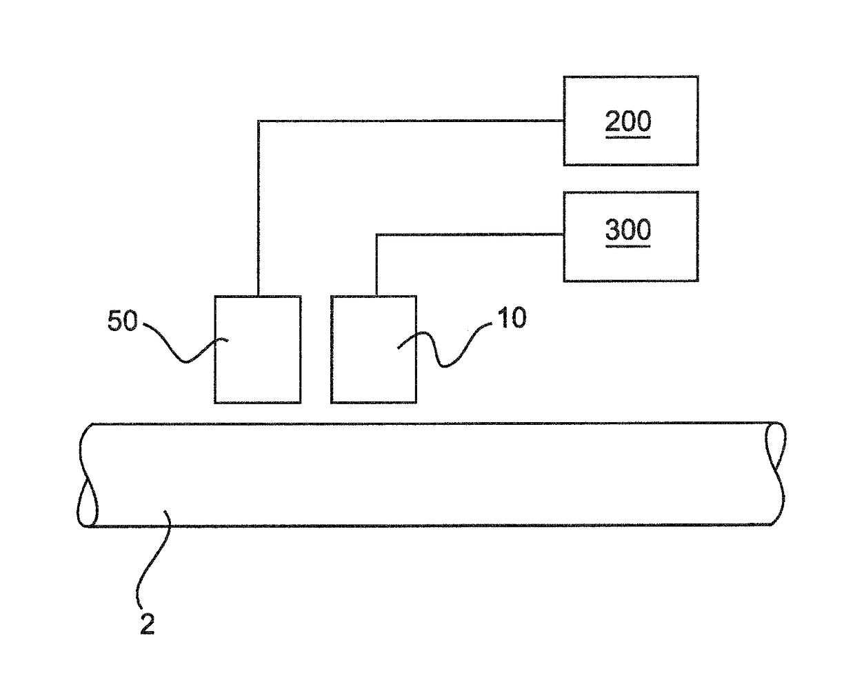
[0072]This patent application describes a magnetic principle based non-contact mechanical force sensing technology that no longer requires any type of treatment of a ferromagnetic test object 2 from where the measurements have to be taken and is very low complexity in design. The following terminology will be used in this specification: sensor, sensor unit, sensing module, sensor system, and test object.

[0073]The sensing module has to be placed nearest to the test object. The test object is the item from where mechanical forces have to be measured. Together, the sensor and the test object will build a sensor system. The test object is a ferromagnetic material like a power transmitting shaft where the mechanical forces have to be measured from. The sensing module is the item that needs to be placed nearest the test object 2 where the mechanical forces have to be measured from. The SCSP electronics is the Signal Conditioning and Signal Processing electronics.

[0074]As can be seen in FI...


PUM


Abstract

A sensor device is for measuring forces applied to an object to be sensed. The sensor device, includes a magnetic field generating element, a magnetic field sensing element, a driving unit being adapted to drive the magnetic field generating element with a first and second driving signal having a first and second frequency, and an evaluation unit. The sensor device is able of compensating a hysteresis of the object to be sensed.

Description

TECHNICAL FIELD[0001]The present description relates to a device and a method for hysteresis compensated force sensing, and in particular to a device and a method for automatic compensation of a hysteresis related deviation of sensing signals at magnetic field based force sensing.TECHNICAL BACKGROUND[0002]Hysteresis is a known phenomenon in ferromagnetic materials like iron (Fe), nickel (Ni), cobalt (Co) and their alloys. It is the inability of the material to return back to its original state when an external force or magnetic field previously applied to it is removed. Hysteresis can occur due to the mechanical pressure applied on the material (elastic hysteresis) and also due to the applied magnetic field (magnetic hysteresis).[0003]In any sensor design and development industry, it is critical for the sensing unit to be capable of measuring the best signal without noise or other distortions. Noise can be compensated by the implementation of analogue filters and also by software al...

Claims


Application Information

Patent Timeline
IPC IPC(8): G01L1/12G01L25/00
CPCG01L1/127G01L25/00G01L3/105
Inventor MAY, LUTZ
Owner TORQUE & MORE TAM
Why Eureka
Try Eureka