
Locking sub-assembly for closing the remaining gap between the first and the last of a blade ring which are inserted in a circumferential groove of a turbomachine, and corresponding turbomachine

a technology of locking sub-assembly and blade ring, which is applied in the direction of liquid fuel engine, vessel construction, marine propulsion, etc., can solve the problems of saving production costs, and achieve the effect of reliably and durably enduring high mechanical stresses, simple and inexpensively achieved

Inactive Publication Date: 2012-04-17
SIEMENS AG
View PDF12 Cites 8 Cited by
  • Summary
  • Abstract
  • Description
  • Claims
  • Application Information

AI Technical Summary

Benefits of technology

"The invention is a locking sub-assembly for a blade ring in a turbomachine that can securely close the remaining gap between the blade ring and the last blade. The sub-assembly is simple and inexpensive to create and can be easily disengaged from the blade ring without being damaged. The sub-assembly is made up of interlocking pieces that are easily inserted and can be reused. The sub-assembly achieves a reliable and durable connection to the blade ring and prevents displacement of the blade ring during operation. The sub-assembly can be secured against disengagement from the blade ring and is designed to fill the gap between the blade ring and the last blade. The sub-assembly is secured against displacement by a locking element that is interconnected to the pieces. The locking element can be a pin-like element or a set of pin-like elements that interconnect the pieces. The sub-assembly is designed to withstand high mechanical loads and can be easily disconnected and reused."

Problems solved by technology

Furthermore, all the pieces which have already been used once can be used again, which saves production costs.

Method used


Image

  • Locking sub-assembly for closing the remaining gap between the first and the last of a blade ring which are inserted in a circumferential groove of a turbomachine, and corresponding turbomachine
  • Locking sub-assembly for closing the remaining gap between the first and the last of a blade ring which are inserted in a circumferential groove of a turbomachine, and corresponding turbomachine
  • Locking sub-assembly for closing the remaining gap between the first and the last of a blade ring which are inserted in a circumferential groove of a turbomachine, and corresponding turbomachine

Examples


Embodiment Construction

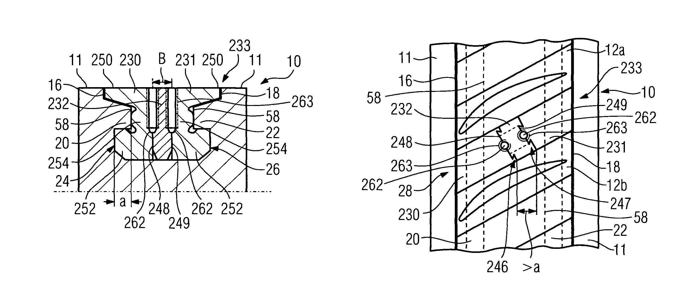
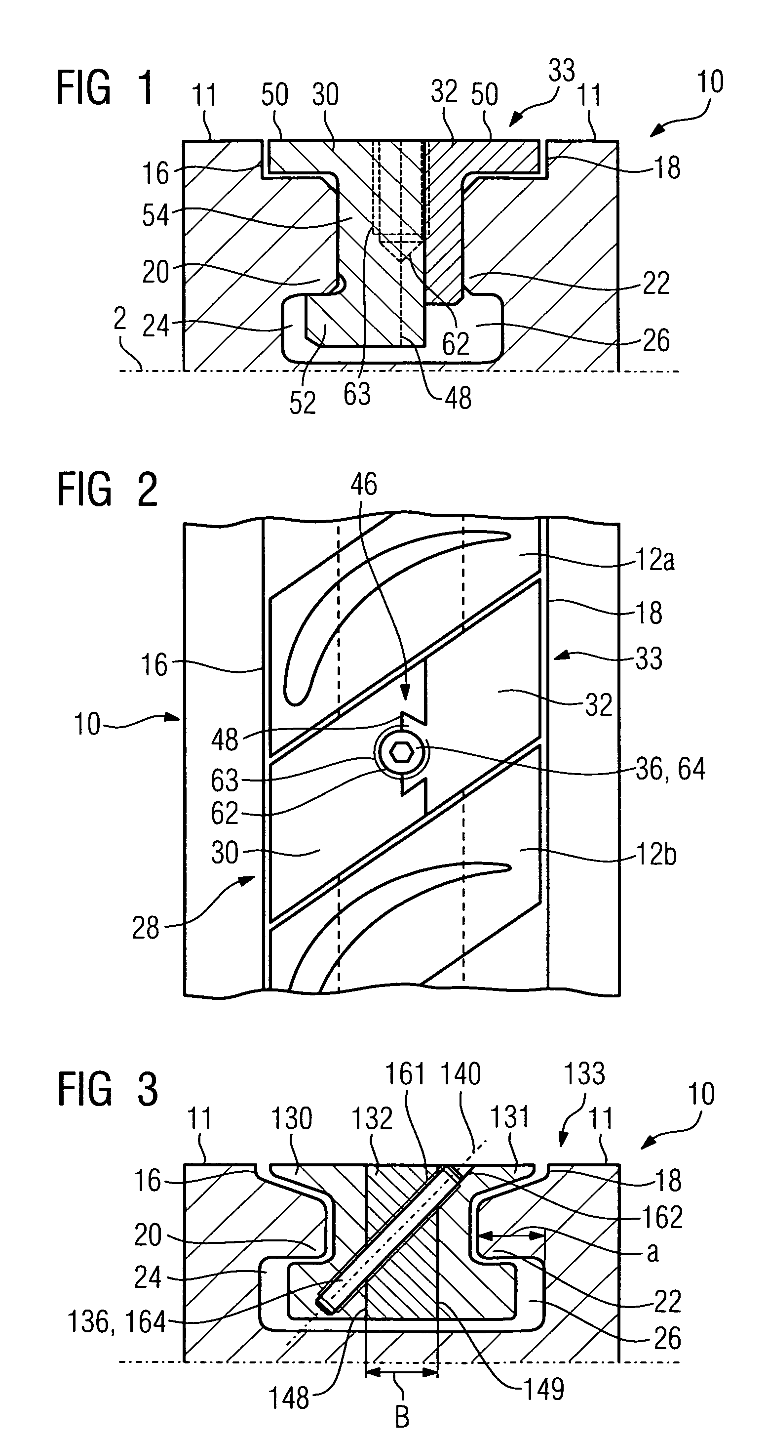
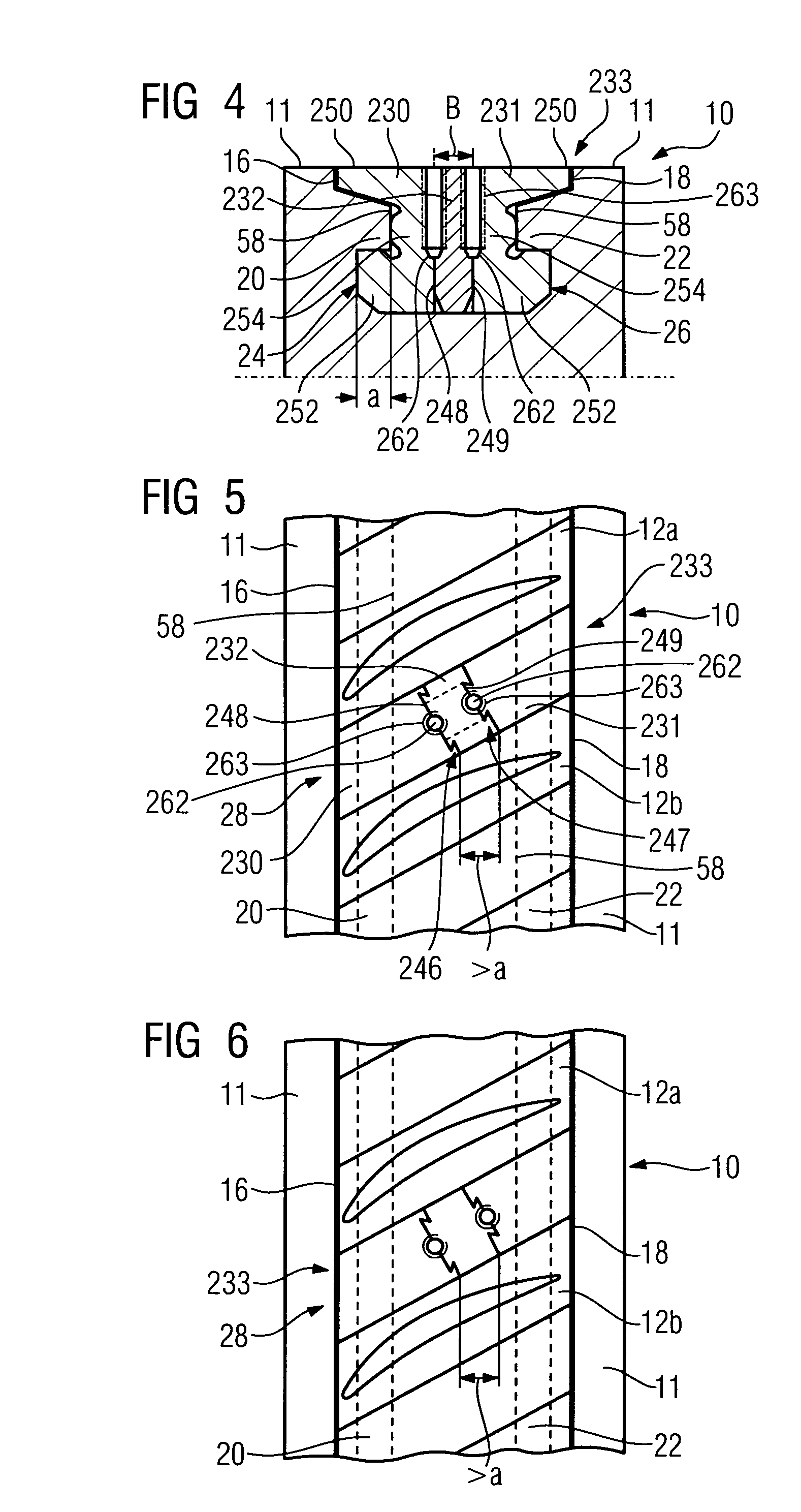
[0035]FIG. 2, FIG. 5 and FIG. 6 show in each case a detail of a plan view of a circumferential groove 10, in which rotor blades 12a, 12b of an axial compressor of a gas turbine are inserted. Instead of the compressor, the invention could also be applied in a steam turbine or in a turbine unit of the gas turbine.

[0036]The endlessly encompassing circumferential groove 10 is provided on an external surface 11 of the rotor of the compressor. The circumferential groove 10 could also be provided on an annular inner casing of the compressor, in which stator blades are fastened. The circumferential groove 10, as seen in the axial direction of the rotor, has a front side wall 16 and a rear side wall 18 upon which projections 20, 22, which extend in the circumferential direction and extend in the axial direction, are arranged in each case and respectively form a front and a rear undercut 24, 26 (FIG. 1, FIG. 3 and FIG. 4).

[0037]Rotor blades 12a, 12b, which have inverted T-shaped blade roots w...


PUM


Abstract

A closing assembly is provided. The closing assembly closes the gap remaining between the first blade and the last blade of a blade ring that is inserted in a peripheral groove of a turbo machinery, the assembly consisting of at least two lateral parts, at least one of which may be hooked onto a projection that forms an undercut in the peripheral groove and at least one securing element, which secures the parts from coming detached from the peripheral groove. To provide a particularly reliable closing assembly, the securing element is configured as a pin, joining the parts of the closing assembly in a non-positive fit.

Description

CROSS REFERENCE TO RELATED APPLICATIONS[0001]This application is the US National Stage of International Application No. PCT / EP2006 / 070226, filed Dec. 27, 2006 and claims the benefit thereof. The International Application claims the benefits of European application No. 06000025.4 filed Jan. 2, 2006, both of the applications are incorporated by reference herein in their entirety.FIELD OF INVENTION[0002]The invention relates to a locking sub-assembly for closing the remaining gap between the first and the last blade of a blade ring which are inserted in a circumferential groove of a turbomachine, which sub-assembly comprises at least two side pieces, of which at least one can be interlocked with a projection, which forms an undercut, of the circumferential groove, and at least one locking element which secures the pieces against disengaging from the circumferential groove.BACKGROUND OF THE INVENTION[0003]Locking sub-assemblies of such generic type for example originate from EP 1 457 64...

Claims


Application Information

Patent Timeline
Patent Type & Authority Patents(United States)
IPC IPC(8): B64C11/04F03B3/12F04D29/34
CPCF01D5/3038F01D5/32F01D9/042
Inventor KRUTZFELDT, JOACHIMKUNZE, MARKUSMARTIN, SILVIO-ULRICHMUTKE, STEFANQIAN, KANGRICHTER, CHRISTOPHSCHNEIDER, OLIVERSCHRODER, PETERSCHWARZ, MICHAELWALTKE, ULRICH
Owner SIEMENS AG
Learn More