
System and method for deploying side airbag of vehicle

a technology for side airbags and vehicles, which is applied in the direction of vehicle components, pedestrian/occupant safety arrangements, vehicular safety arrangments, etc., can solve the problems of passenger injuries, vehicle body deformation, passenger injuries, etc., and achieve the effect of preventing an injury of a passenger

Active Publication Date: 2015-05-28
HYUNDAI MOTOR CO LTD +1
View PDF27 Cites 3 Cited by
  • Summary
  • Abstract
  • Description
  • Claims
  • Application Information

AI Technical Summary

Benefits of technology

The present invention is a system and method for deploying a side airbag in a vehicle. The system can detect a crash and lower the threshold for deploying the side airbag simultaneously with the front airbag, based on an acceleration signal in the longitudinal direction of the vehicle. This allows for timely deployment of the side airbag even if the signal sensed by a side crash sensor or a side pressure sensor is small. The invention can prevent potential injuries to passengers during crashes of various angles and speeds, providing safety measures for vehicles.

Problems solved by technology

Although this airbag deploying system is mounted in a vehicle, due to a small magnitude of signals sensed from local crashes of various angles and speeds from actual crash accidents, the side airbag may not be deployed, thus causing damage or an injury to a vehicle body and a passenger.
In spite of a situation in which the side airbag in addition to the front airbag needs to be deployed, the side airbag may not be deployed, thus causing deformation of a vehicle body and injury of passengers.
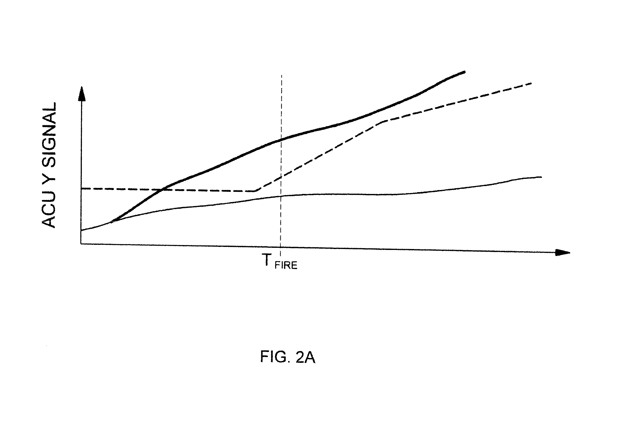
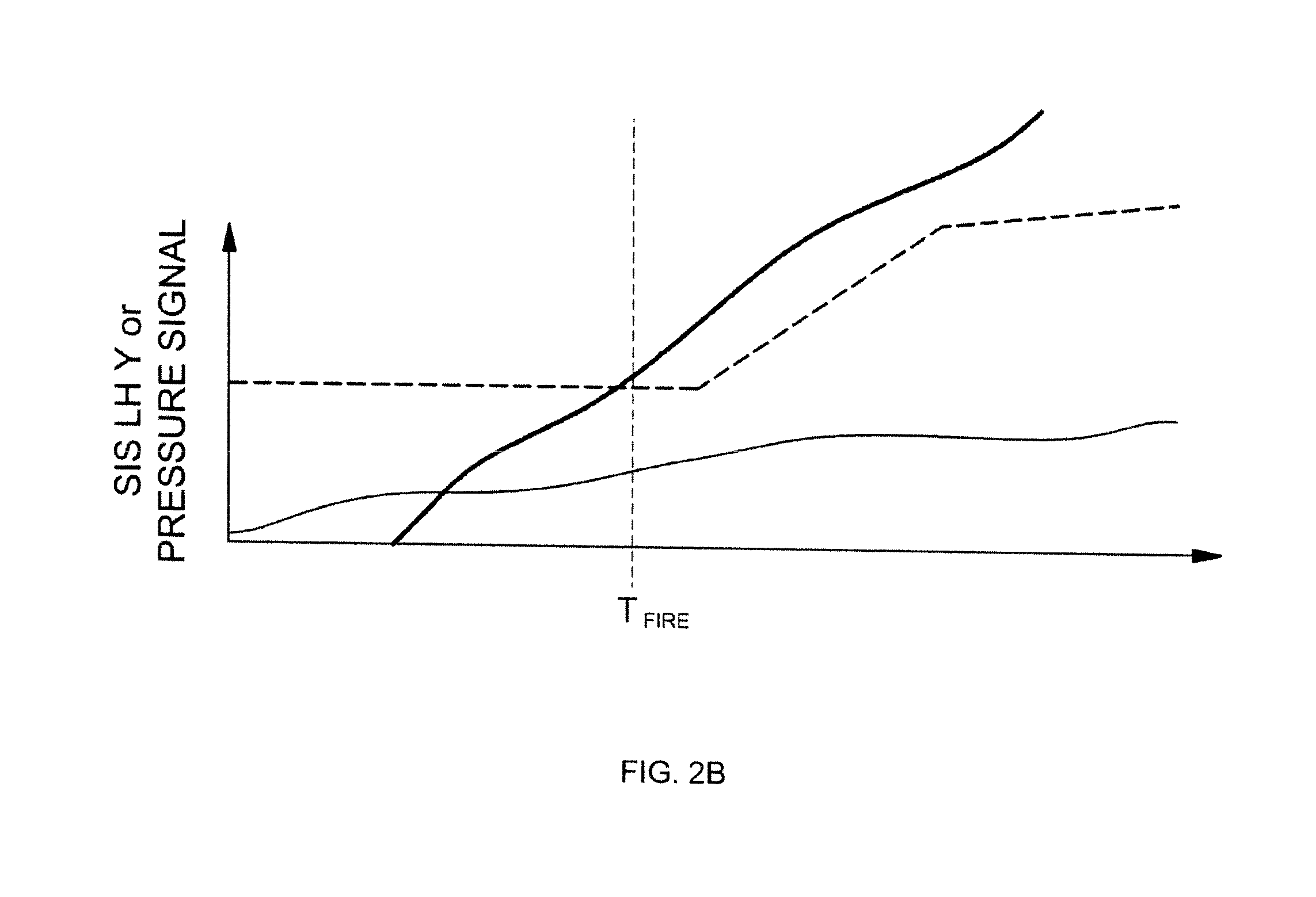
In this case, since a direction impact is not applied in the lateral direction of the vehicle body, the sensed values of the Y-direction acceleration and pressure do not exceed a predetermined threshold, making it impossible to deploy the side airbag, and thus causing deformation of the vehicle body and injury of passengers.

Method used


Image

  • System and method for deploying side airbag of vehicle
  • System and method for deploying side airbag of vehicle
  • System and method for deploying side airbag of vehicle

Examples


Embodiment Construction

[0030]Hereinafter, reference will now be made in detail to various embodiments of the present disclosure, examples of which are illustrated in the accompanying drawings and described below. While the disclosure will be described in conjunction with exemplary embodiments, it will be understood that present description is not intended to limit the disclosure to those exemplary embodiments. On the contrary, the disclosure is intended to cover not only the exemplary embodiments, but also various alternatives, modifications, equivalents, and other embodiments, which may be included within the spirit and scope of the disclosure as defined by the appended claims.

[0031]It is understood that the term “vehicle” or “vehicular” or other similar term as used herein is inclusive of motor vehicles in general such as passenger automobiles including sports utility vehicles (SUV), buses, trucks, various commercial vehicles, watercraft including a variety of boats and ships, aircraft, and the like, an...


PUM


Abstract

A system for deploying a side airbag of a vehicle comprises a front / side airbag controller for controlling processes of deploying a front airbag and a side airbag independently. The front / side airbag controller comprises a front signal monitoring unit converting a front acceleration signal received from the airbag controller into a speed according to time and then determining whether or not the speed according to time exceeds a first threshold. A threshold adjustment unit receives a threshold adjustment request signal from the front signal monitoring unit to lower a second threshold that is a threshold with respect to decision factors for deploying the side airbag.

Description

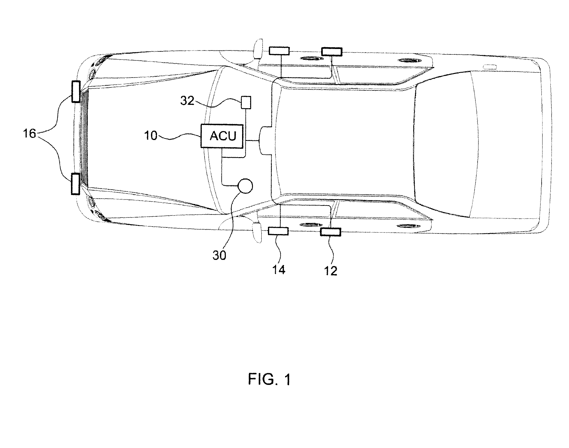
CROSS-REFERENCE TO RELATED APPLICATION[0001]This application claims under 35 U.S.C. §119(a) the benefit of priority to Korean Patent Application No. 10-2013-0144237 filed on Nov. 26, 2013, the entire contents of which are incorporated herein by reference.TECHNICAL FIELD[0002]The present disclosure relates to a system and method for deploying a side airbag of a vehicle. More particularly, the present disclosure relates to a system and method for deploying a side airbag of a vehicle, which can prevent an injury of a passenger by lowering a threshold for deploying the side airbag based on a front acceleration signal upon crash.BACKGROUND[0003]Generally, airbags are deployed to prevent injury of passengers upon crash of vehicles, which include front airbags including a driver airbag and a passenger airbag and a side (curtain) airbag that is deployed upon a side crash.[0004]Referring to FIG. 1, an airbag deploying system includes a front crash sensor 16 disposed on a vehicle bumper, i.e....

Claims


Application Information

Patent Timeline
IPC IPC(8): B60R21/0132
CPCB60R21/0132B60R21/0136B60R21/21B60R2021/0004B60R2021/01211B60R2021/01327
Inventor PARK, HYUNG WOOKKIM, SUNG SOO
Owner HYUNDAI MOTOR CO LTD
Learn More