Floating fastener mounting structure

a technology of fastener and mounting structure, which is applied in the direction of fastening means, screws, sheet joining, etc., can solve the problems of screw dropping from the metal panel members, affecting the re-installation operation of the next panel member,

Active Publication Date: 2015-05-28
HANWIT PRECISION IND LTD
View PDF11 Cites 4 Cited by
  • Summary
  • Abstract
  • Description
  • Claims
  • Application Information

AI Technical Summary

Benefits of technology

[0010]The present invention has been accomplished under the circumstances in view. It is therefore the main object of the present invention to provide a floating fastener mounting structure, which facilitates quick installation and provides high structural strength and enhanced shear strength, avoiding accidental breaking.
[0011]To achieve this and other objects of the present invention, the floating fastener mounting structure comprises a metal panel member and a mounting socket. The metal panel member defines a convex wall portion and a mounting through hole cut through the convex wall portion. The mounting socket comprises a center hole vertically extending through the opposing top and bottom sides thereof, an annular step and a stop flange extended around the outer perimeter thereof at different elevations, and an annular locating groove defined between the annular step and the stop flange. The mounting socket is riveted to the metal panel member to force the annular locating groove into engagement with the convex wall portion, enabling the convex wall portion to be tightly stopped between the annular step and the stop flange. The annular step defines a downwardly and outwardly sloping top surface for guiding the convex wall portion of the metal panel member into engagement with the annular locating groove of the mounting socket in the rivet operation. After riveting, the convex wall portion of the metal panel member is engaged into the annular locating groove and tightly stopped between the annular step and the stop flange to prohibit the mounting socket from displacement relative to the metal panel member, enhancing the structural strength of the connection area between the mounting socket and the metal panel member and the shear strength of the whole assembly against breaking.
[0013]In an alternate form of the present invention, the aforesaid C-shaped retainer is eliminated, and the lock screw is fixedly mounted with a cap member that is axially slidably coupled to the mounting socket. The cap member is affixed to the head of the lock screw and axially slidably coupled to the outer perimeter of the mounting socket between an external top annular flange and the annular step of the mounting socket.

Problems solved by technology

The lock screws of the fastening devices may fall from the metal panel members and missed easily due to user's negligence during a metal panel member dismounting procedure for the performance of a repair or speed adjustment operation, affecting further re-installation operation.

Method used


Image

  • Floating fastener mounting structure
  • Floating fastener mounting structure
  • Floating fastener mounting structure

Examples


Embodiment Construction

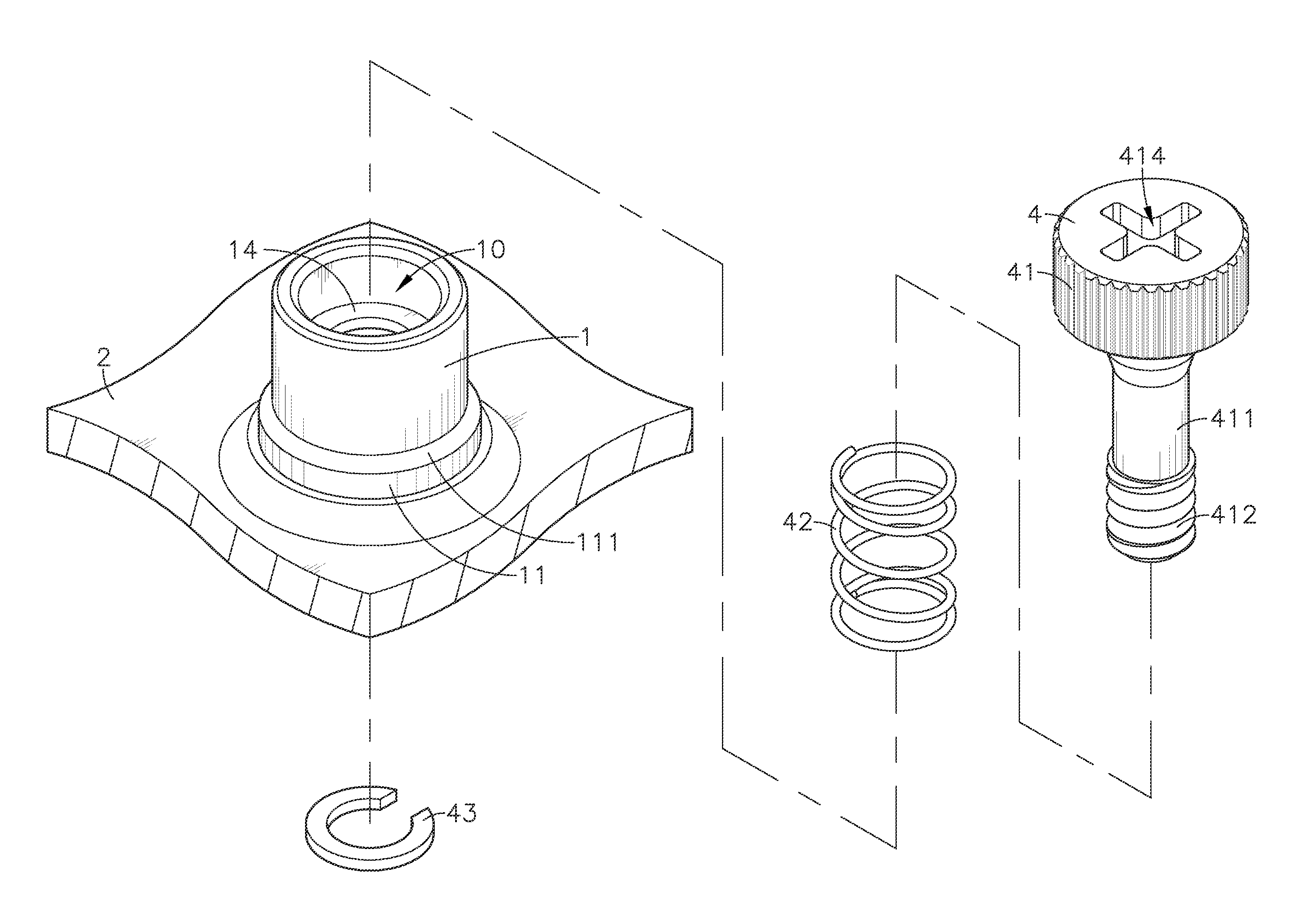
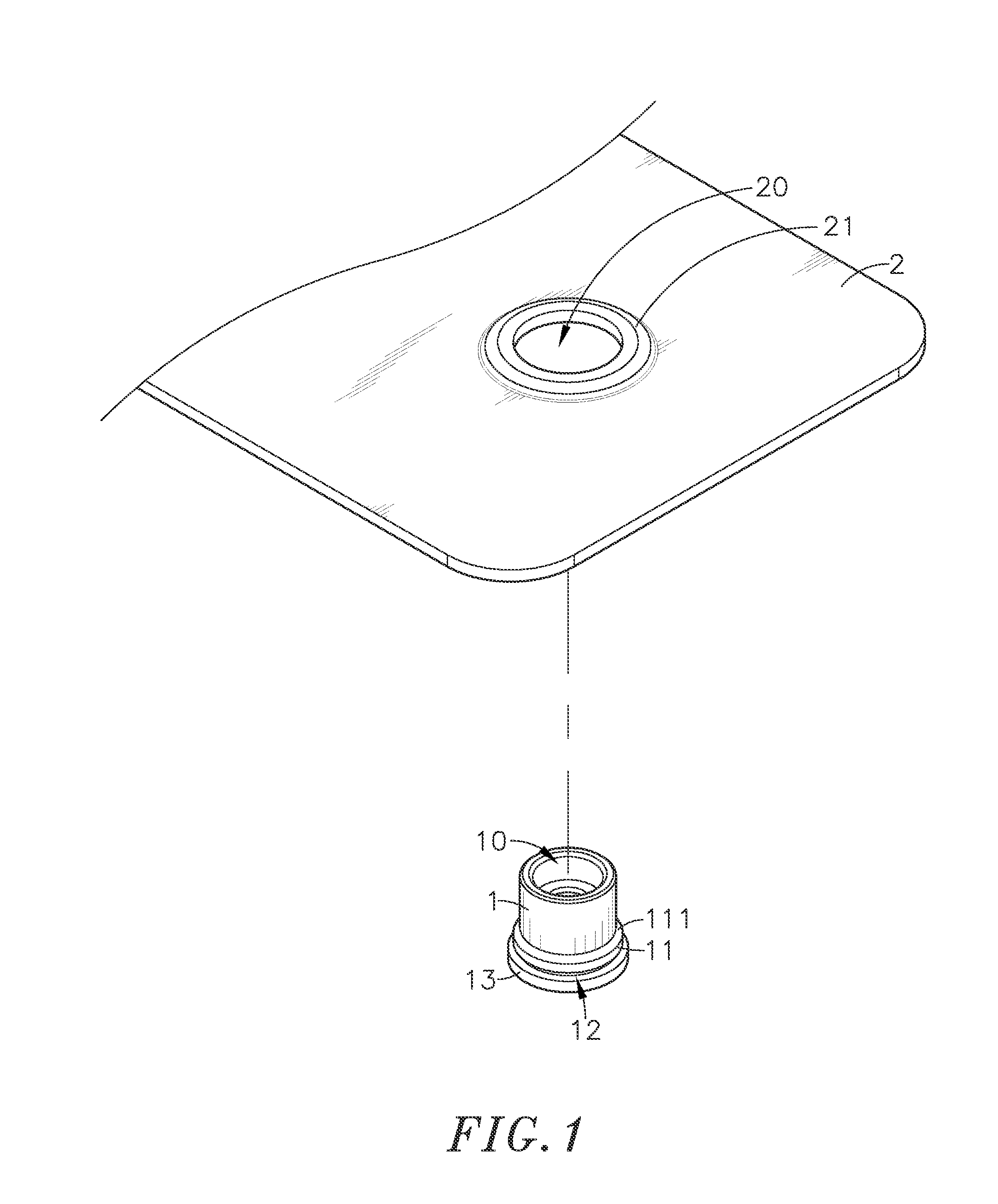
[0022]Referring to FIGS. 1, 2 and 3, a floating fastener mounting structure in accordance with the present invention comprises a mounting socket 1, and a metal panel member 2.

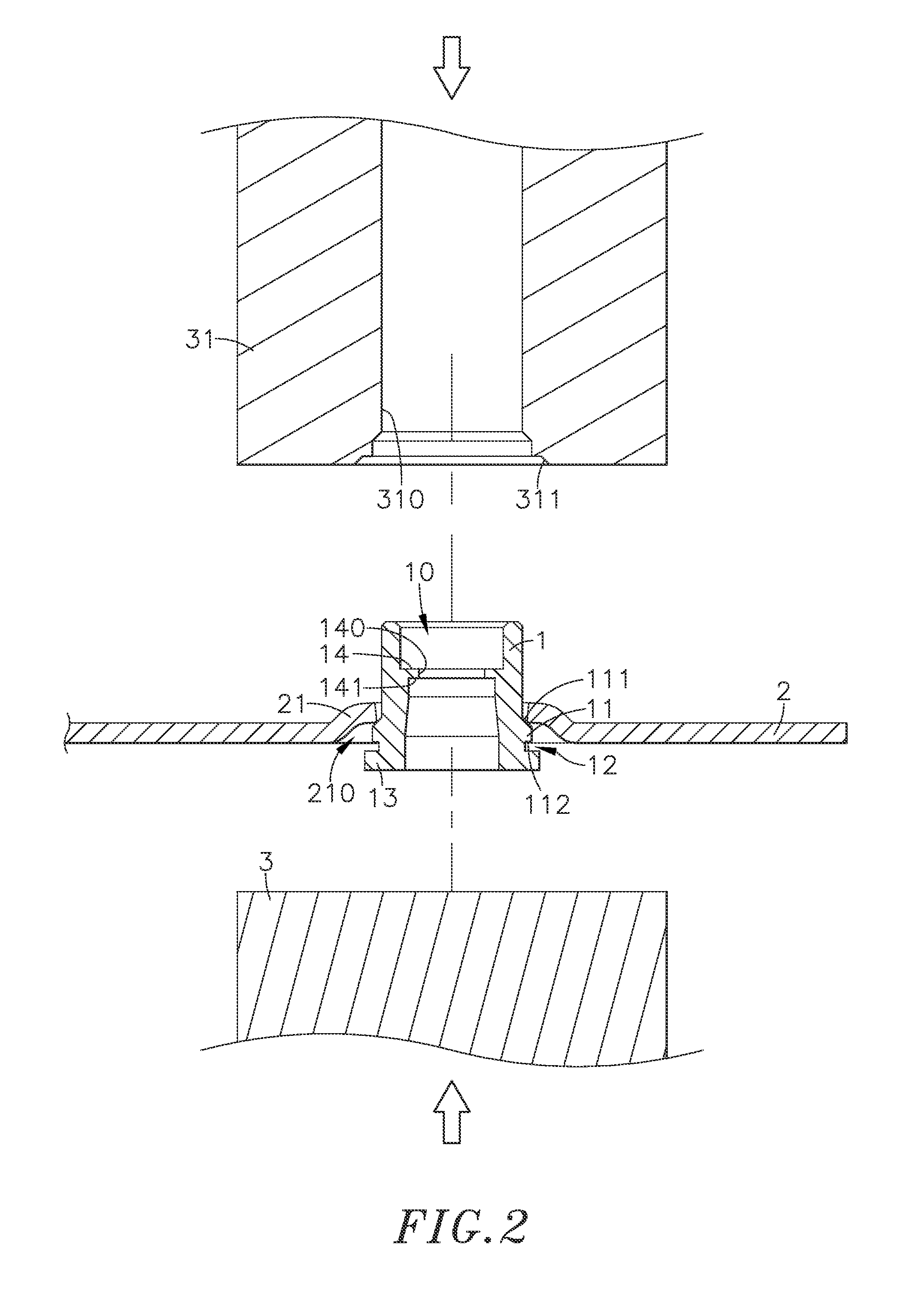
[0023]The mounting socket 1 is an open-ended cylindrical member comprising a center hole 10 vertically extending through opposing top and bottom sides thereof, an annular step 11 extended around the outer perimeter thereof at a selected elevation, a stop flange 13 extended around the outer perimeter in flush with the bottom wall of the mounting socket, and a annular locating groove 12 extended around the outer perimeter between the annular step 11 and the stop flange 13. The outer diameter of the stop flange 13 is larger than the outer diameter of the annular step 11. Further, the annular step 11 defines a downwardly and outwardly sloping top surface 111.

[0024]The metal panel member 2 comprises a mounting through hole 20, and a convex wall portion 21 disposed around the mounting through hole 20 and defining a b...


PUM

PropertyMeasurementUnit
outer diameteraaaaaaaaaa
horizontal displacementaaaaaaaaaa
perimeteraaaaaaaaaa

Abstract

A floating fastener mounting structure includes a metal panel member defining a convex wall portion and a mounting through hole at the convex wall portion, a mounting socket including an axially extended center hole, an annular step and a stop flange extended around the periphery at different elevations and an annular locating groove defined between the annular step and the stop flange. The mounting socket is riveted to the metal panel member to force the annular locating groove into engagement with the convex wall portion, enabling the convex wall portion to be tightly stopped between the annular step and the stop flange. The annular step defines a downwardly and outwardly sloping top surface for guiding the convex wall portion of the metal panel member into engagement with the annular locating groove of the mounting socket in the rivet operation.

Description

[0001]This application is a Continuation of Application No. 13 / 607,759, filed on Sep. 9, 2012, for which priority is claimed under 35 U.S.C. §120, the entire contents of which are hereby incorporated by reference.BACKGROUND OF THE INVENTION[0002]1. Field of the Invention[0003]The present invention relates to floating fastener mounting technology and more particularly, to a floating fastener mounting structure that enhances the strength of the connected structure between a mounting socket and a metal panel member, wherein the mounting socket comprises an annular step and a stop flange extended around the periphery thereof at different elevation, and a annular locating groove defined between the annular step and the stop flange; the metal panel member comprises a mounting through hole for the insertion of the mounting socket, and a convex wall portion disposed around the mounting through hole engaged into the annular locating groove of the mounting socket and tightly stopped between t...

Claims


Application Information

Patent Timeline
Patent Type & Authority Applications(United States)
IPC IPC(8): F16B5/02
CPCF16B5/0208Y10T29/49948
Inventor TSENG, YING-CHIH
Owner HANWIT PRECISION IND LTD
Why Eureka
Try Eureka