Electric compressor for vehicle air conditioner

Active Publication Date: 2015-05-28
TOYOTA IND CORP
View PDF3 Cites 0 Cited by
  • Summary
  • Abstract
  • Description
  • Claims
  • Application Information

AI Technical Summary

Benefits of technology

The present invention provides an electric compressor for vehicles that can be mounted in the engine compartment. It includes a compression mechanism, an electric motor, a motor driving circuit, a housing, two mounting legs, and a connecting portion. The mounting legs are designed to be easily connected to the engine and housing. The connecting portion of the first mounting leg is designed to break more easily than the second mounting leg. This design helps to absorb the impact of a collision and protect the electric compressor from damage.

Problems solved by technology

If any external force is applied to the vehicle and the electric compressor is moved in the engine compartment by receiving force transmitted from the vehicle, the compressor may collide against objects therearound such as an auxiliary machine and be damaged at the housing which accommodates a motor driving circuit, and the force may be transmitted to the motor driving circuit.

Method used


Image

  • Electric compressor for vehicle air conditioner
  • Electric compressor for vehicle air conditioner
  • Electric compressor for vehicle air conditioner

Examples


Embodiment Construction

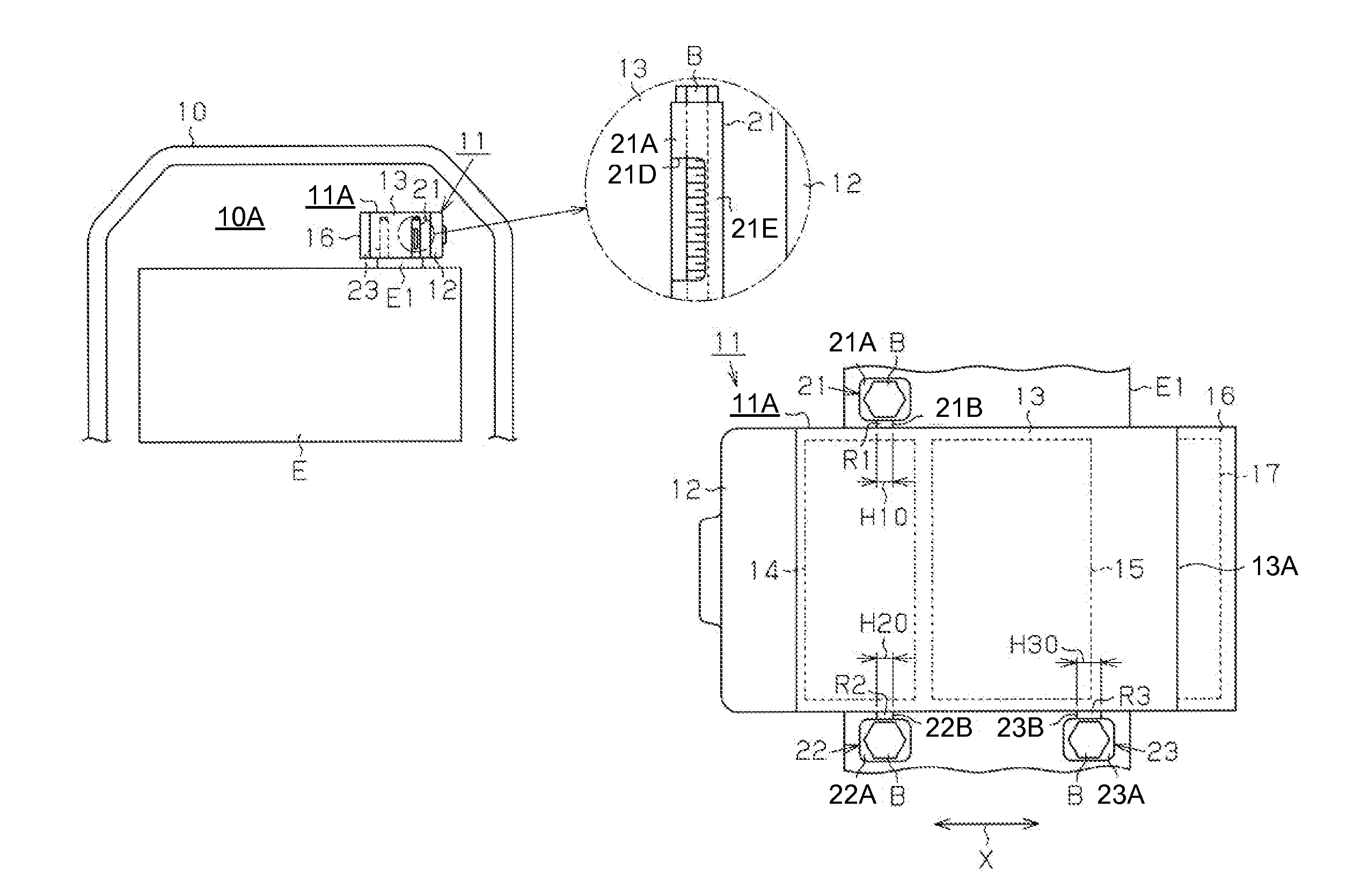
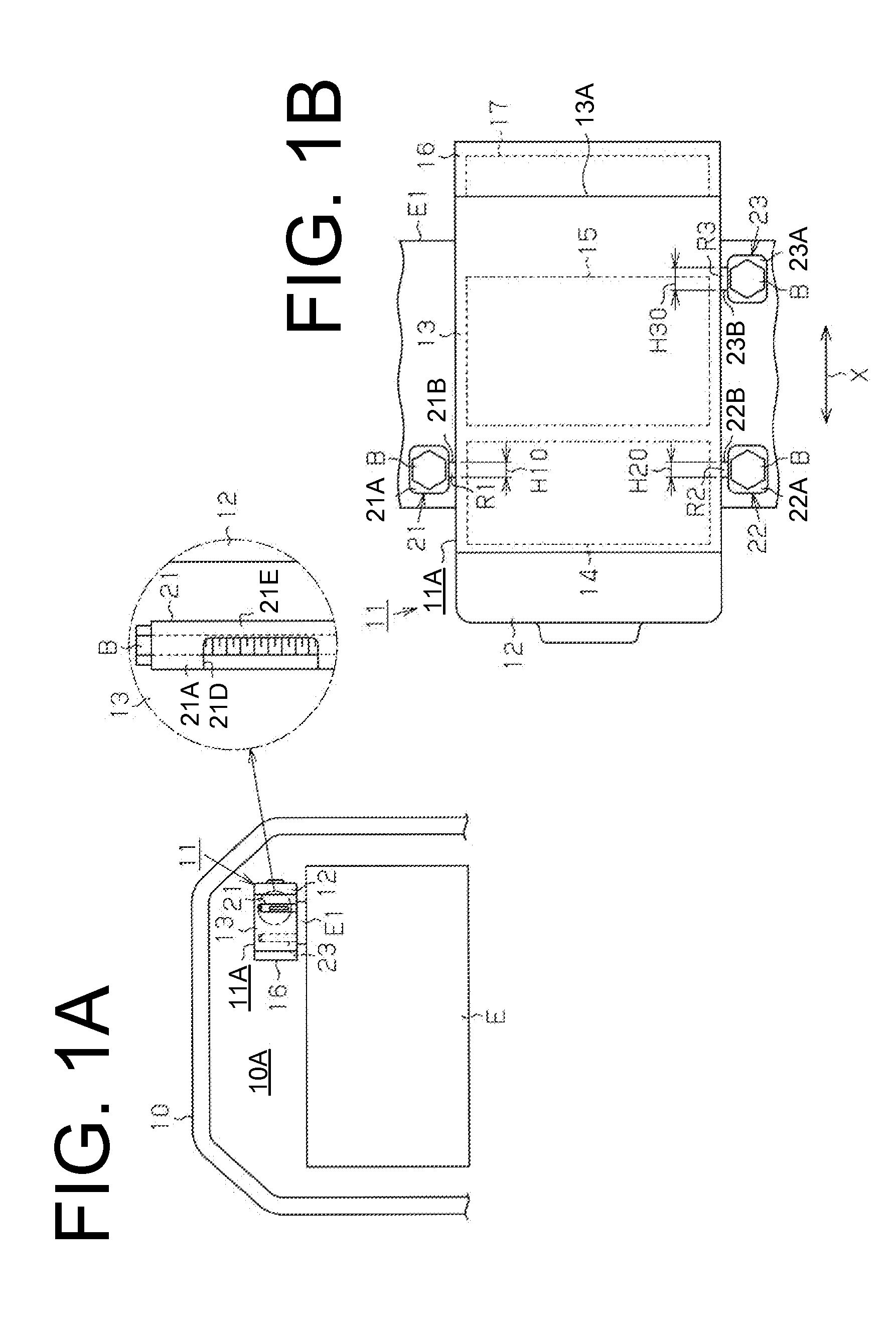
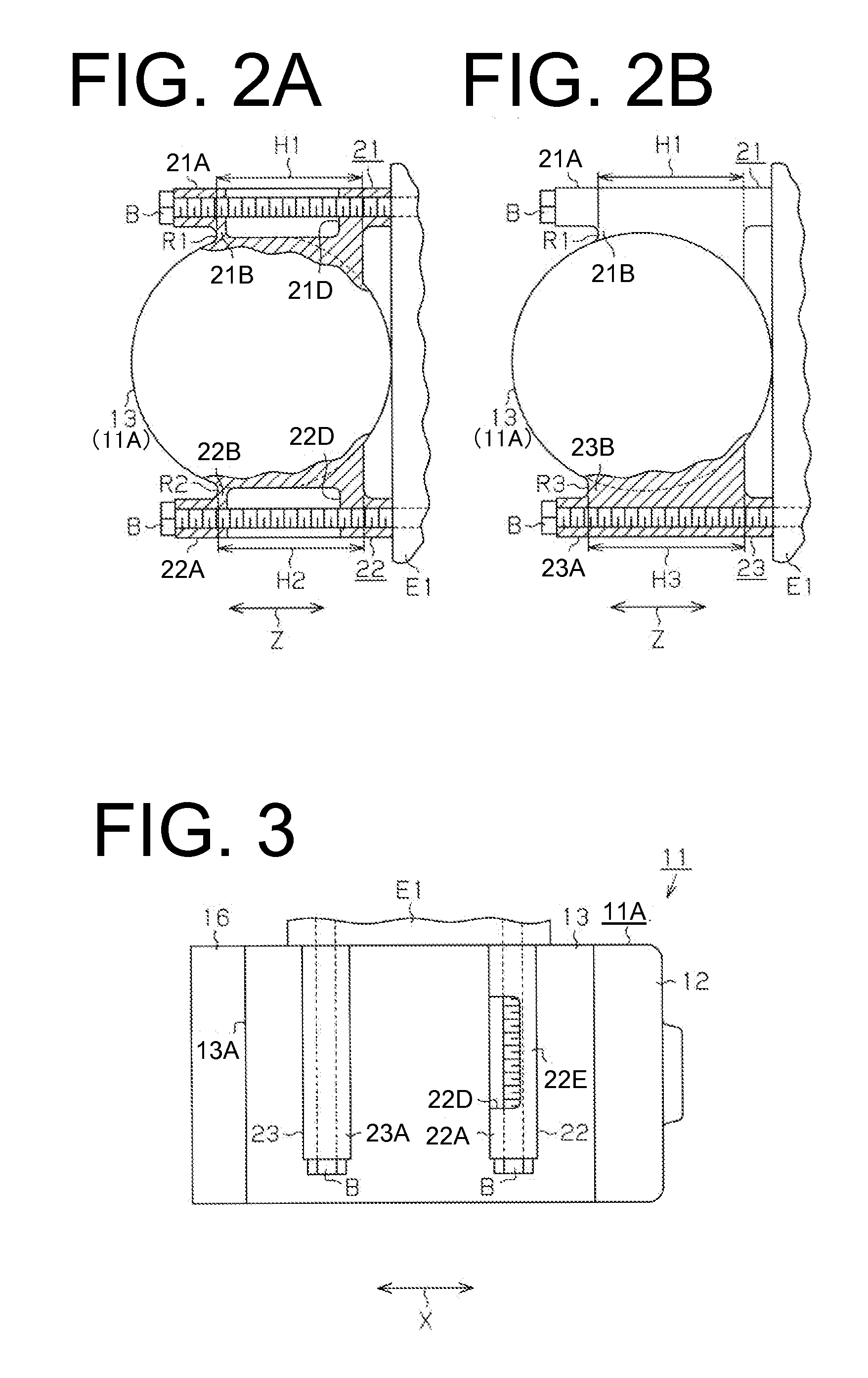
[0012]The following will describe an embodiment of the present invention with reference to FIG. 1A to FIG. 3. Referring to FIG. 1A, numeral 10 designates a vehicle having therein an engine compartment 10A and an engine E is disposed in the engine compartment 10A. The engine E has a block E1 and an electric compressor 11 is fixed or fastened to the block E1. Thus, the block E1 serves as the portion of the engine E to which the electric compressor 11 is fastened.

[0013]As shown in FIG. 1B, the electric compressor 11 has a housing 11A that includes a cylindrical discharge housing 12, a cylindrical suction housing 13 and a cylindrical cover 16, each of which has a closed end. The suction housing 13 is connected to the discharge housing 12 and the cover 16 is mounted on a bottom wall 13A of the suction housing 13. The discharge housing 12, the suction housing 13 and the cover 16 are made of aluminum (metal material). The suction housing 13 accommodates therein a compression mechanism 14 t...


PUM


Abstract

An electric compressor to be mounted on an engine in an engine compartment of a vehicle includes a compression mechanism, an electric motor, a motor driving circuit, a housing, a first mounting leg and a second mounting leg. The housing accommodates therein the compression mechanism, the electric motor and the motor driving circuit. The first mounting leg projects from the housing at a position adjacent to the compression mechanism. The second mounting leg projects from the housing at a position adjacent to the motor driving circuit. Each of the first mounting leg and the second mounting leg includes a fastening portion to be fastened to a portion of the engine and a connecting portion that connects the fastening portion with the housing. The connecting portion of the first mounting leg is made to be broken more easily than connecting portion of the second mounting leg.

Description

BACKGROUND OF THE INVENTION[0001]The present invention relates to an electric compressor for vehicle air conditioner.[0002]Japanese Patent Application Publication No. 2004-32494 discloses an electric compressor used for a vehicle air conditioner. This type of compressor has a housing that is formed with a plurality of mounting legs projecting from the housing. Each mounting leg includes a fastening portion to which a corresponding portion of an engine is fastened and a connecting portion which connects the fastening portion to the housing. The electric compressor is mounted on the engine in an engine compartment of the vehicle by fastening the fastening portions to the respective portion of the engine.[0003]If any external force is applied to the vehicle and the electric compressor is moved in the engine compartment by receiving force transmitted from the vehicle, the compressor may collide against objects therearound such as an auxiliary machine and be damaged at the housing which ...

Claims


Application Information

Patent Timeline
IPC IPC(8): F04C2/02F04C15/00
CPCF04C15/0057F04C2/025F01C21/007F04B35/04F04B39/121F04B39/14F04C18/0215F04C23/008F04C28/28F04C2240/805F04C2240/808Y10S248/909
Inventor YAMASHITA, TAKUROINAGAKI, TOMOYOSHI
Owner TOYOTA IND CORP
Why Eureka
Try Eureka