Drip irrigation emitter and drip irrigation device equipped with same

a technology of drip irrigation and emitter, which is applied in the direction of watering devices, horticulture, agriculture, etc., can solve the problems of limited amount of drip irrigation, achieve the effect of preventing capillary at the inlet, properly restricting the inflow of irrigation liquid, and improving the degree of freedom of material selection of the inflow par

Inactive Publication Date: 2015-06-04
ENPLAS CORP
View PDF8 Cites 24 Cited by
  • Summary
  • Abstract
  • Description
  • Claims
  • Application Information

AI Technical Summary

Benefits of technology

[0028]According to the present invention, even when the liquid pressure of irrigation liquid in a flow pipe is low, drip irrigation can be properly performed.
[0029]With the invention according to [1], the lower limit of the liquid pressure of irrigation liquid that flows in the flow channel of the drip irrigation emitter main body can be controlled, by the hydrophobicity of the inflow part, to a level lower than that of a conventional art. Thus, even when the liquid pressure of the irrigation liquid in the flow pipe (in other words, outside of the flow channel of the drip irrigation emitter main body) is low, the irrigation liquid can be properly used for drip irrigation.
[0030]With the invention according to [2], a portion of the inflow part exposed to the irrigation liquid outside of the flow channel of the drip irrigation emitter main body has hydrophobicity. Thus, the inflow of the irrigation liquid into the flow channel of the drip irrigation emitter main body can be properly limited.
[0031]With the invention according to [3], capillarity at the inlet can be surely prevented and thus the inflow of the irrigation liquid can be properly limited.
[0032]With the invention according to [4], the hydrophobicity of the inflow part can be achieved with a small number of components.
[0033]With the invention according to [5], the hydrophobicity of the inflow part does not depend on the material of the inflow part, and thus the degree of freedom of selection of the material of the inflow part can be improved.

Problems solved by technology

As a result, the ejection amount is limited.

Method used


Image

  • Drip irrigation emitter and drip irrigation device equipped with same
  • Drip irrigation emitter and drip irrigation device equipped with same
  • Drip irrigation emitter and drip irrigation device equipped with same

Examples


Embodiment Construction

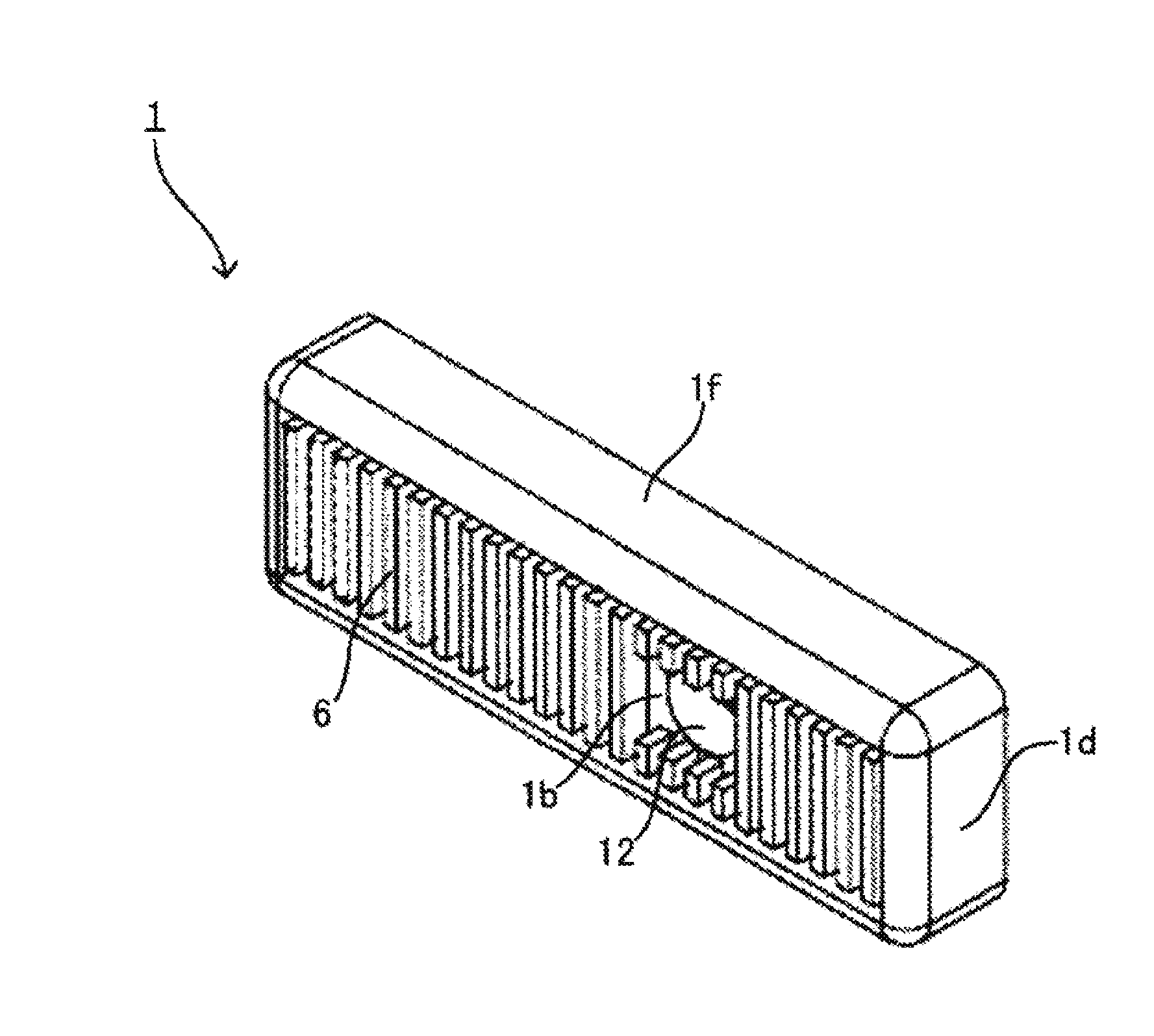
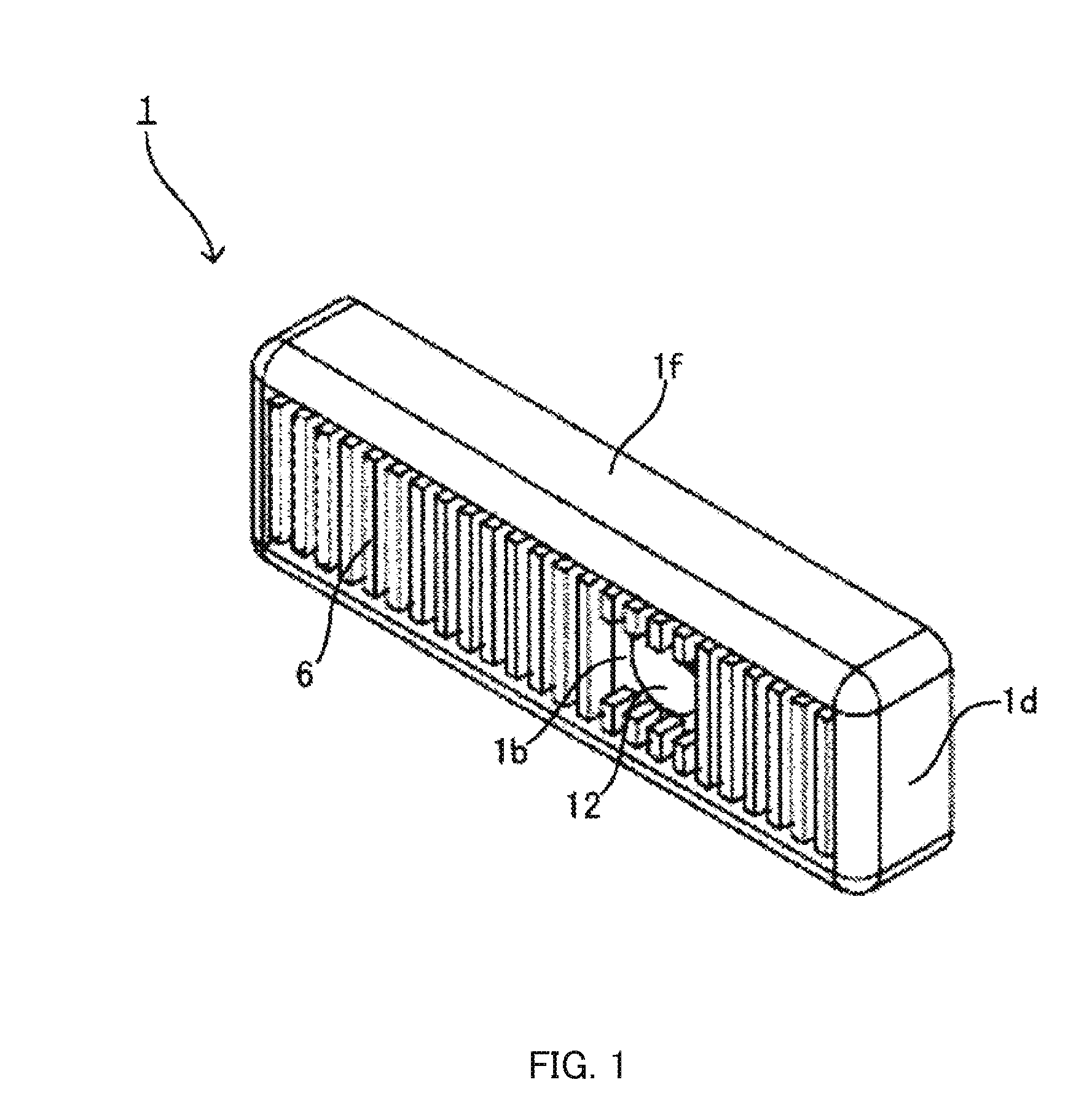
[0055]In the following, a drip irrigation emitter according to Embodiment of the present invention and a drip irrigation apparatus including the drip irrigation emitter will be described with reference to FIGS. 1 to 12.

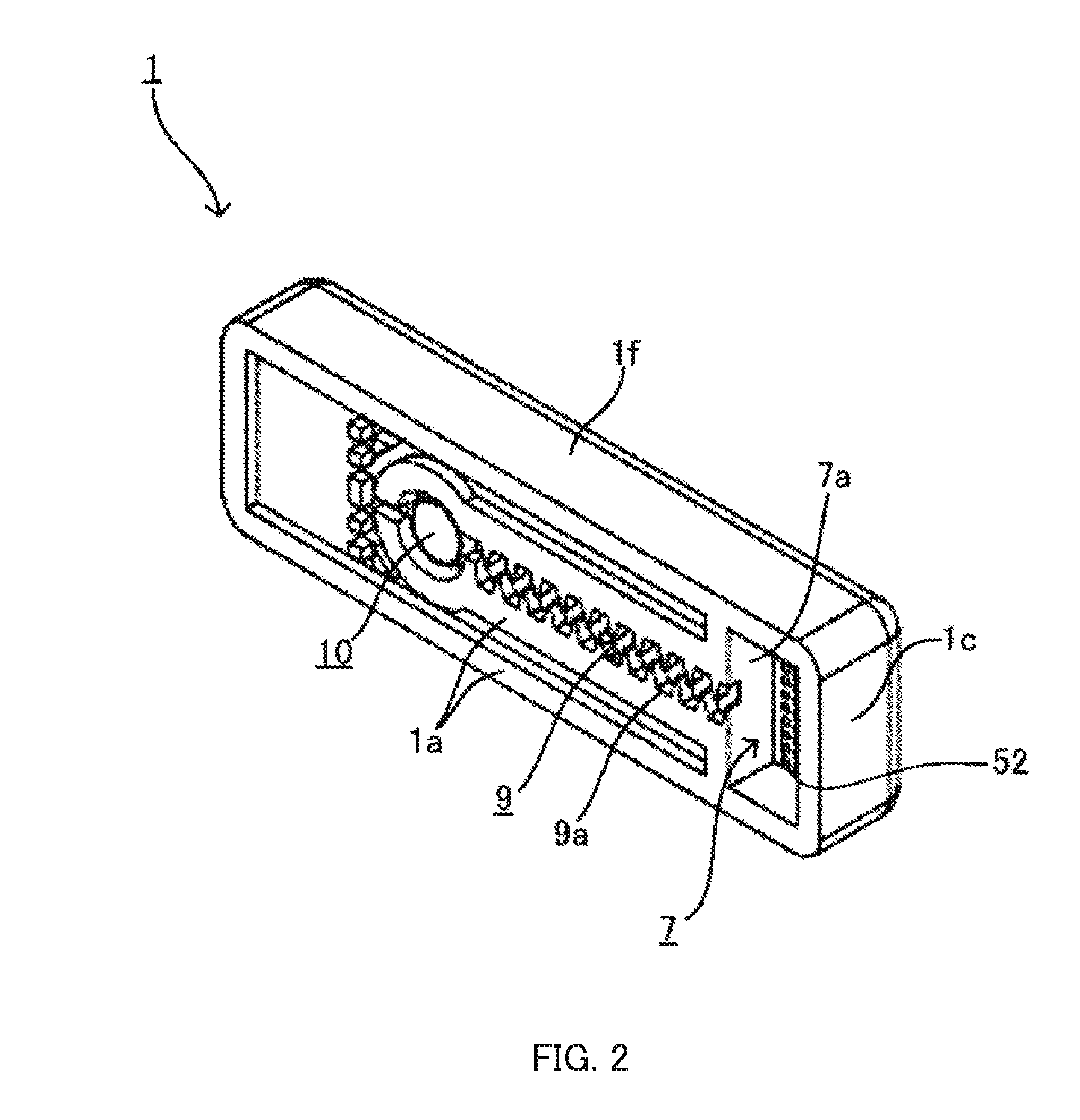
[0056]FIG. 1 is a perspective view of drip irrigation emitter 1 in Embodiment as viewed from the top side of drip irrigation emitter 1. FIG. 2 is a perspective view of drip irrigation emitter 1 as viewed from the bottom side of drip irrigation emitter 1. FIG. 3 is a plan view of drip irrigation emitter 1. FIG. 4 is a sectional view of drip irrigation emitter 1 taken along line A-A of FIG. 3. FIG. 5 is a bottom view of drip irrigation emitter 1. FIG. 6 is a sectional view schematically illustrating drip watering tube 2 as the drip irrigation apparatus in Embodiment.

[0057]As illustrated in FIG. 6, drip watering tube 2 includes substantially cylindrical and elongated tube main body 3 serving as a flow pipe through which the irrigation liquid flows, and drip irrigation em...


PUM


Abstract

A drip irrigation emitter (1), which comprises a low pressure stop filter (5), a pressure reduction channel (8), and a diaphragm (10), is disposed on the inner wall surface of a flow pipe (3) through which the irrigation liquid flows. The low pressure stop filter (5) has a hydrophobic surface and prevents inflow of the irrigation liquid when the fluid pressure is lower than an established value. The pressure reduction channel (8) reduces the pressure of the irrigation liquid. The diaphragm (10) changes the degree of opening of the pressure reduction channel (8) according to the fluid pressure of the irrigation liquid. The drip irrigation emitter (1) can be manufactured at low cost as a result of being a one-piece molding. The drip irrigation device comprising the drip irrigation emitter (1) stably ejects the irrigation liquid even when the liquid pressure is low.

Description

TECHNICAL FIELD[0001]The present invention relates to a drip irrigation emitter and a drip irrigation apparatus including the drip irrigation emitter, and particularly to a drip irrigation emitter and a drip irrigation apparatus including the drip irrigation emitter which are suitable for growing plants.BACKGROUND ART[0002]Conventionally, drip irrigation systems (also known as trickle irrigation systems or micro irrigation systems) have been employed to supply water and irrigation liquid such as liquid fertilizer to the plants to be grown into the soil in the agricultural land, the plantation or the like.[0003]In such drip irrigation systems, for example, a filter, a fertigation apparatus (a chemigation apparatus if necessary), a back flow prevention apparatus, a main pipe, and the like are connected in sequence on the downstream side of a pump that brings up water from the water source, and an elongated drip watering tube is connected to the channel terminal. In addition, the drip ...

Claims


Application Information

Patent Timeline
Patent Type & Authority Applications(United States)
IPC IPC(8): A01G25/02
CPCA01G25/023Y02A40/22A01G25/026A01G25/02
Inventor KIDACHI, MASAHIRO
Owner ENPLAS CORP
Why Eureka
Try Eureka