Optical filter lock and environmental seal

a technology of optical filter and seal, which is applied in the direction of camera filters, mountings, instruments, etc., can solve the problems of sealing preventing undesired loosening of filters, and achieve the effect of effectively preventing air, dust and other pollutants

Inactive Publication Date: 2015-06-04
MAMIYA AMERICA CORP
View PDF1 Cites 14 Cited by
  • Summary
  • Abstract
  • Description
  • Claims
  • Application Information

AI Technical Summary

Benefits of technology

[0006]To overcome these issues, the present invention aims to provide an optical filter assembly (including at least one camera lens filter), which is capable of camera lens sealing protection, so as to effectively prevent air, dust and other pollutants from reaching the front of the camera lens. In addition, the present invention also provides a seal to secure the optical filter assembly to the camera lens barrel in such a way that the assembly also will not dismount itself due to vibration, use or other operating conditions.
[0007]In order to realize the above mentioned aim, according to an aspect of the invention, the assembly includes a kind of camera lens filter, included in a filter frame having a first end and a second end opposite the first end. The first end of the filter frame is provided with a connecting device, the inner wall of the filter frame is provided with a clamp mounting portion and an optic mounting part along the axial direction. The rear facing part of the filter assembly has a male thread that is half the connecting device—the other part being the female thread on the front of the lens barrel. Optical components, such as a filter, are installed on the optic mounting part; a clamp is mounted on the clamp mounting portion, and when manually engaged presses tightly against the optical component to secure it. As indicted above the thread on the outside of the filter frame may be the connecting device, the clamp may be the retaining ring part that presses against the filter or the sealing O-ring to lock the glass filter (or other material filter) into the filter frame. A first sealing mechanism is provided between the optical component and the optic mounting part for positively locking down the optical component. The optical mounting part may essentially be a flat surface inside the filter frame that one side of the glass filter rests against. In one embodiment, this sealing mechanism is an O-ring. A second sealing mechanism is also provided, is located on the outer wall of the filter frame, and preferably seals by pressing against and friction locking the filter assembly to the front of the camera lens barrel to which it is being mounted. In one embodiment, the sealing mechanisms may each be an O-ring. In combination, the first and second sealing mechanisms form seals to preclude dust and other materials from entering the lens area and adhering to the lens. In addition, these seals preclude undesired loosening of the filter.
[0011]To facilitate the installation of the first sealing mechanism, which is preferably a circular sealing ring with a circular or oval shape in cross-section, preferably, there is a first groove on the first surface that is opposite to the optical component, and the first sealing mechanism is mounted using the first groove.
[0014]Similarly, in order to facilitate installation of the second sealing mechanism, especially to better position the sealing mechanism which is also preferably a sealing ring of a circular or oval shape cross-section, preferably, a second sealing mechanism mounting part is set on the outer wall of the filter frame, and the second sealing mechanism is mounted in the second groove.
[0017]In conclusion, the present invention includes placing the first sealing mechanism between the camera filter lens and the inside of the filter frame and / or setting the second sealing mechanism on the outer wall of the filter frame, which is used to seal the gap between the camera lens barrel and the camera lens filter frame, so as to prevent air, dust and other pollutants from reaching the front surface of the camera lens along the connected parts of the optical component and filter frame and / or the connected parts of the camera lens barrel and filter frame, effectively providing the sealing protection for the front of the camera lens and preventing dismount of the camera lens filter itself due to vibration, use or other operating conditions.

Problems solved by technology

In addition, these seals preclude undesired loosening of the filter.

Method used


Image

  • Optical filter lock and environmental seal
  • Optical filter lock and environmental seal
  • Optical filter lock and environmental seal

Examples


Embodiment Construction

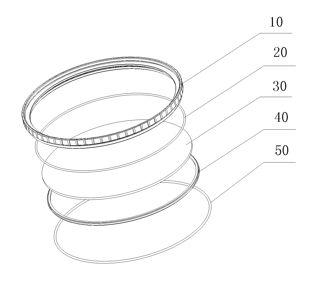
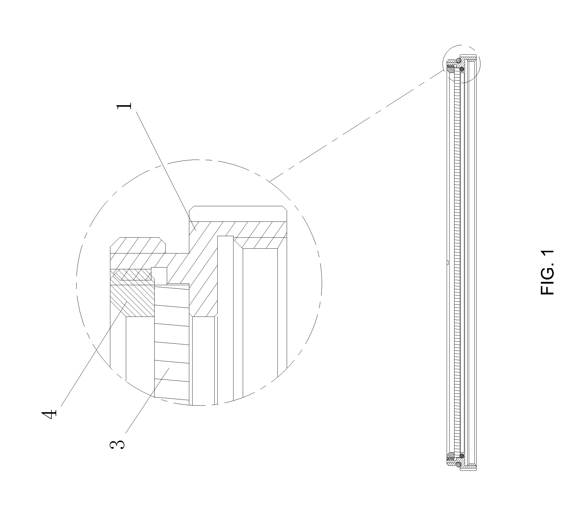
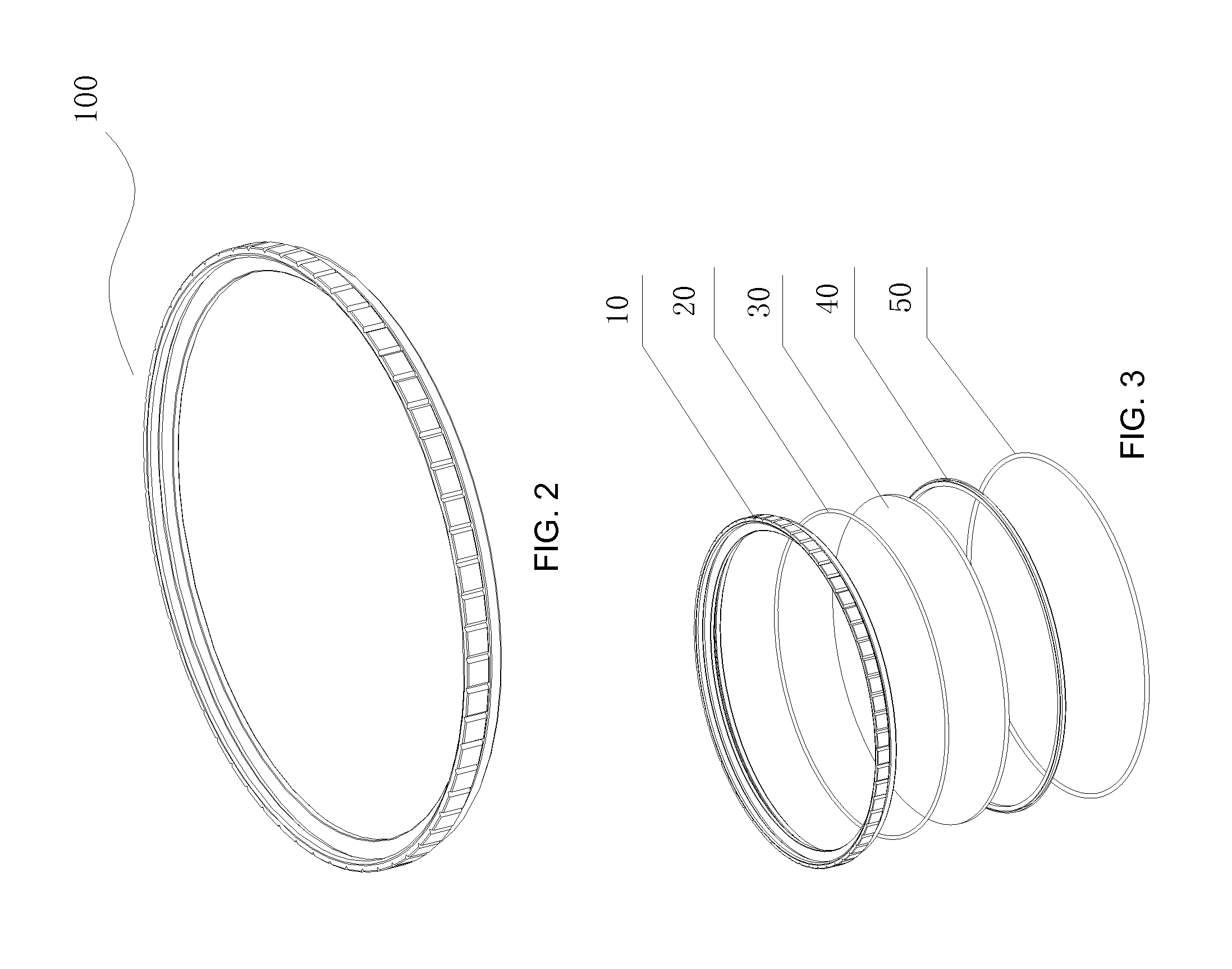
[0025]As shown in FIGS. 2-4b, the present invention provides a camera lens filter assembly 100, which provides structure and support for component parts including filter frame 10, first sealing ring 20, optical component 30, clamp 40 and second sealing ring 50. In which, as shown in FIG. 4a and FIG. 4b, the filter frame 10 includes first end 201 and second end 202 opposite the first end. The first end of filter frame 10 includes a connecting device to connect with camera lens barrel 60. The clamp mount and optic mount are set along the axial direction of the inner wall of filter frame 10, optical component 30 is mounted on an optic mount system, clamp 40 is mounted on clamp mount system, and clamp 40 can lock optical component 30. In which, the first sealing mechanism included between optical component 30 and optic mount system seals the gap between optical component 30 and filter frame 10, which can prevent air, dust and other pollutants from reaching the from surface of the camera...


PUM


Abstract

The present invention is directed to a camera lens filter assembly including a camera lens filter and an included optical component. The optical component is installed on an optic mounting part; and a clamp is mounted on a clamp mounting part, so the clamp can press to tighten against the optical component for the purpose of assembly. The present invention efficiently prevents air, dust and other environmental pollutants from reaching the front surface of the camera lens and will also seal to secure the camera lens filter to the camera lens barrel in a way that it will not dismount itself due to vibration, use or other operating conditions.

Description

[0001]The present invention claims priority to China Patent Application No. 201320775779.5, filed Nov. 29, 2013, which is incorporated herein by reference.[0002]The present invention relates to photo, film and video camera equipment, and in particular an externally mounted optical filter assembly and its attachment to a camera lens.BACKGROUND OF THE PRESENT INVENTION[0003]A camera lens filter is a frequently used piece of photographic equipment which is typically attached in front of a photographic lens by a screw thread to the camera lens barrel. Optical filters are mainly used for blocking unwanted radiation (i.e., ultra violet or UV), to protect the front element of a camera lens and / or to adjust the photographic effect in a way that would be difficult or impossible to do by camera controls alone. A conventional existing camera lens filter, as shown in FIG. 1, is comprised of frame 1, optical component (typically but not limited to a flat filter or thin lens) 3 and clamp 4 to sec...

Claims


Application Information

Patent Timeline
Patent Type & Authority Applications(United States)
IPC IPC(8): G03B11/00G02B7/02G03B11/04G03B17/12
CPCG03B11/00
Inventor HAO, LIUYI, LUROSE, ROBERT MICHAEL
Owner MAMIYA AMERICA CORP
Why Eureka
Try Eureka