Controller for a fluid distribution system and method of operation thereof

a fluid distribution system and control board technology, applied in lighting and heating apparatus, instruments, heating types, etc., can solve the problems of significant damage to property, waste of water and any energy associated with its heating, and inability to control the operation so as to improve the efficiency of electrical operation and increase the conservation of energy and water. , the effect of increasing the control of electrically operated valves

Inactive Publication Date: 2015-06-04
ULTRAFLO SYST
View PDF10 Cites 8 Cited by
  • Summary
  • Abstract
  • Description
  • Claims
  • Application Information

AI Technical Summary

Benefits of technology

[0014]Presently provided by the invention, a controller for a fluid distribution system and a method of operation thereof that provides an enhanced interface, provides greater control over electrically operated valves of the fluid distribution system, provides for increased conservation of energy and water, and allows customization at the point of use by a user, has surprisingly been discovered.

Problems solved by technology

In environments which use the conventional fluid distribution system, failure of a valve or a pipe may result in significant damage to property, if a fluid within the distribution system is dispersed in the environment without control.
Additionally, conventional fluid distribution systems may include an extensive amount of pipe for use with hot water.
Further, once a request for hot water is received, the hot water pipes may initially absorb a significant amount of heat from the hot water.
In conventional fluid distribution systems, this water and any energy associated with its heating, goes to waste.
Despite the above mentioned benefits, fluid distribution systems including electrically operated valves are not without faults.
Such controllers to date have lacked the simple versatility of manually operated valves.
Additionally, such controllers have not taken advantage of technological improvements now available.
Such interfaces reflected the inherent limitations of the fluid distribution systems including electrically operated valves.
Accordingly, greater control over such a fluid distribution system was limited by such a minimal interface.
However, such calibration only applied to the single point of use corresponding to the calibrated set of valves.
Further, such calibration required adjustment at the location of the valve, not the location of use.
As a result, individual temperature preferences by a plurality of users of the system were impossible to obtain without performing a calibration routine between users.

Method used


Image

  • Controller for a fluid distribution system and method of operation thereof
  • Controller for a fluid distribution system and method of operation thereof
  • Controller for a fluid distribution system and method of operation thereof

Examples


Embodiment Construction

[0028]It is to be understood that the invention may assume various alternative orientations and step sequences, except where expressly specified to the contrary. It is also to be understood that the specific devices and processes illustrated in the attached drawings, and described in the following specification are simply exemplary embodiments of the inventive concepts defined in the appended claims. Hence, specific dimensions, directions or other physical characteristics relating to the embodiments disclosed are not to be considered as limiting, unless the claims expressly state otherwise.

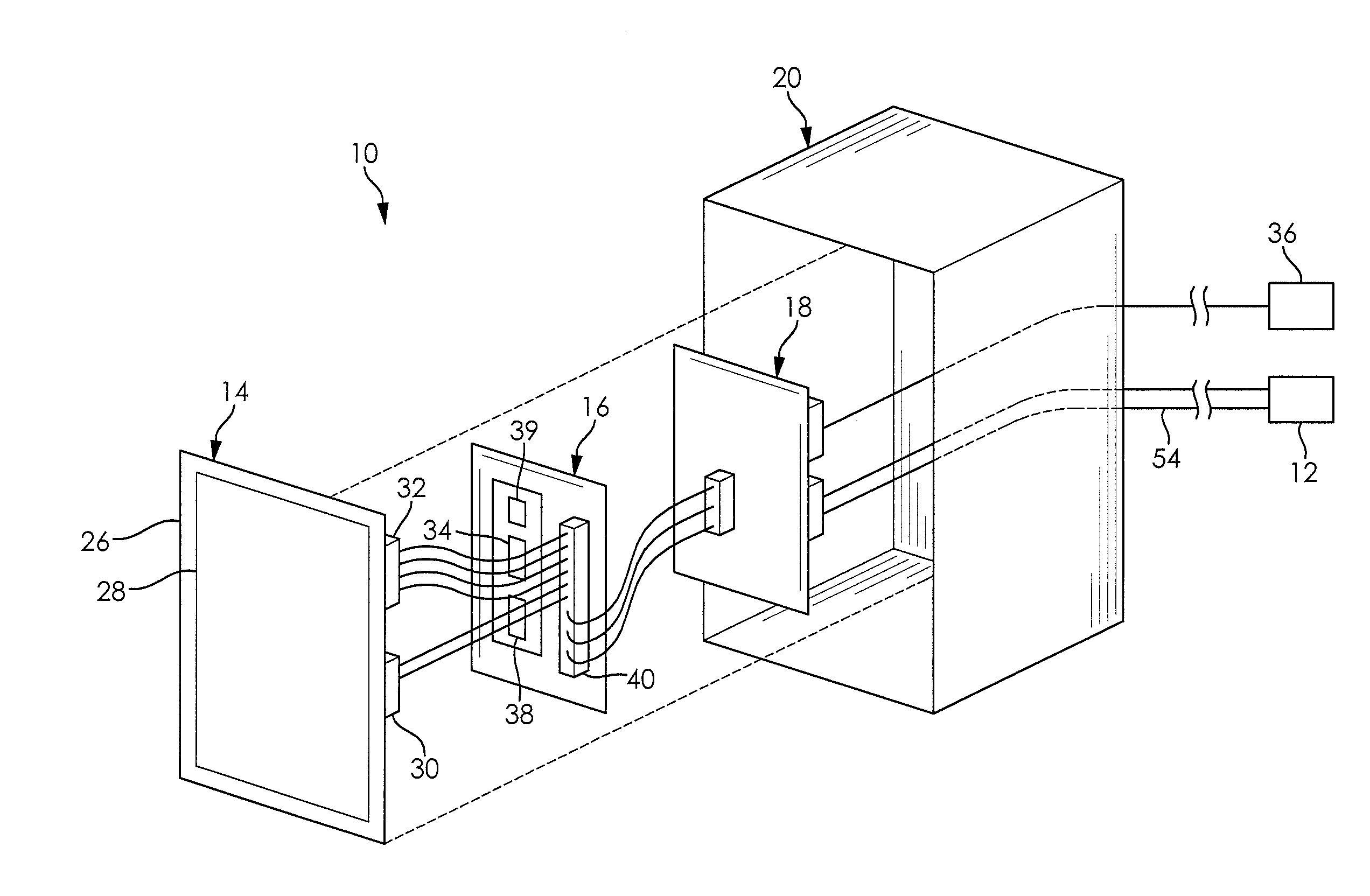
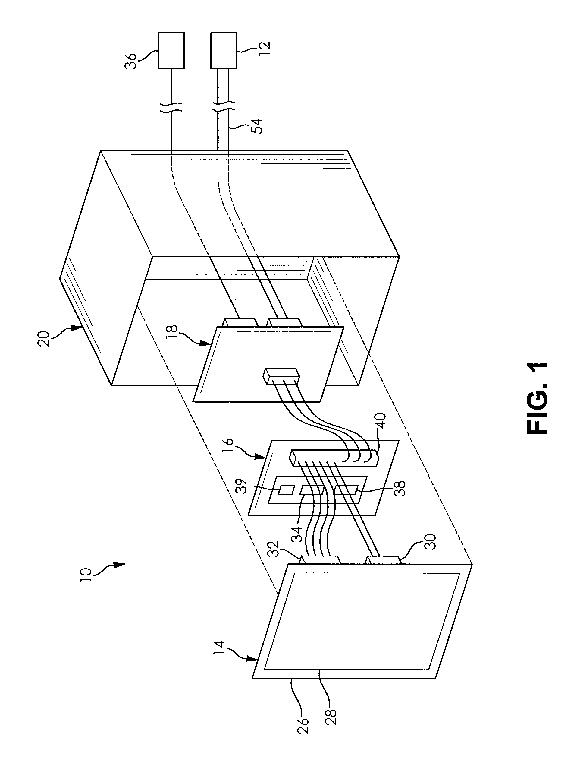
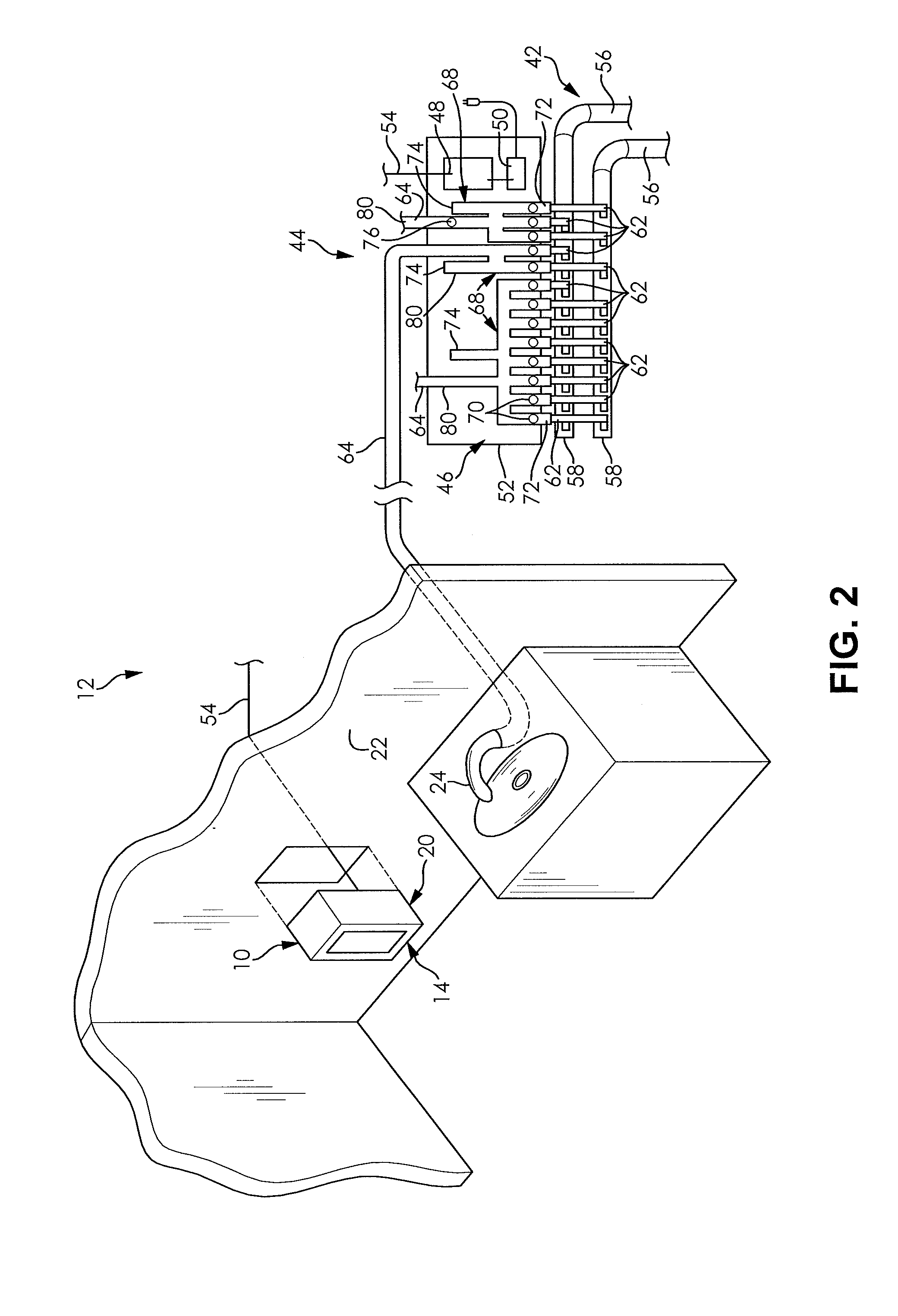
[0029]FIG. 1 illustrates a controller 10 for a fluid distribution system 12 (more clearly illustrated in FIG. 2) according to an embodiment of the invention. The controller 10 comprises a touch screen 14, a processing unit 16, and an output interface 18. The touch screen 14, the processing unit 16, and the output interface 18 are disposed within a controller housing 20. The controller housing 20 i...


PUM


Abstract

A controller for use with a fluid distribution system and method of operation thereof is provided. The controller comprises a touch screen, a processing unit, and an output interface. The processing unit is in communication with the touch screen. The output interface is in communication with the processing unit and the fluid distribution system. In response to a touch input from a user, the processing unit accesses at least one valve profile and adjusts a state of operation of the fluid distribution system through the output interface.

Description

RELATED APPLICATIONS[0001]The present application claims the benefit of U.S. Provisional Application No. 61 / 911,540 filed on Dec. 4, 2013, which is incorporated herein in its entirety by reference.FIELD OF THE INVENTION[0002]The invention relates to fluid distribution systems and, more particularly, to a controller for operating a fluid distribution system and a method of operation thereof.BACKGROUND OF THE INVENTION[0003]Fluid distribution systems are very common in a variety of environments, such as residential homes, offices, and commercial and industrial buildings. Fluid distribution systems rely on a pressurization of a fluid to deliver the fluid to a point of use. Conventionally, manually operated valves operated at the point of use are used to control delivery of the fluid. However, a fluid distribution system including electrically operated valves which are triggered by a user or an automated system may also be used to control delivery of the fluid. U.S. Pat. No. 2,991,481, ...

Claims


Application Information

Patent Timeline
Patent Type & Authority Applications(United States)
IPC IPC(8): G05D7/06G05B15/02
CPCG05B15/02G05D7/0629G05D23/1393E03B7/04F24D3/1066F24D19/1051Y10T137/0318
Inventor DIDION, JOSHUA D.PICKLE, JEFFREY L.
Owner ULTRAFLO SYST
Why Eureka
Try Eureka