QOS control system, QOS control method, and program

a control system and control method technology, applied in the field of qos (quality of service) control system, can solve the problems of overhead virtualization, difficult to provide high communication performance to each virtual machine, and the bandwidth of a physical link between the server b>10/b> and the tor switch may not be appropriately shared among users

Active Publication Date: 2015-06-04
NEC CORP
View PDF2 Cites 29 Cited by
  • Summary
  • Abstract
  • Description
  • Claims
  • Application Information

AI Technical Summary

Benefits of technology

[0023]According to the present disclosure, QoS control over traffic according to the QoS policy can be executed when each virtual machine performs communication using an I / O virtualization technology in a server virtualization environment where the I / O virtualization technology can be used.

Problems solved by technology

In the server virtualization environment, there is overhead for virtualization.
Thus, there is a problem that it is difficult to provide high communication performance to each virtual machine 20.
Further, the bandwidth of a physical link between the server 10 and the ToR switch 12 may not be appropriately shared among the users.

Method used


Image

  • QOS control system, QOS control method, and program
  • QOS control system, QOS control method, and program
  • QOS control system, QOS control method, and program

Examples


first exemplary embodiment

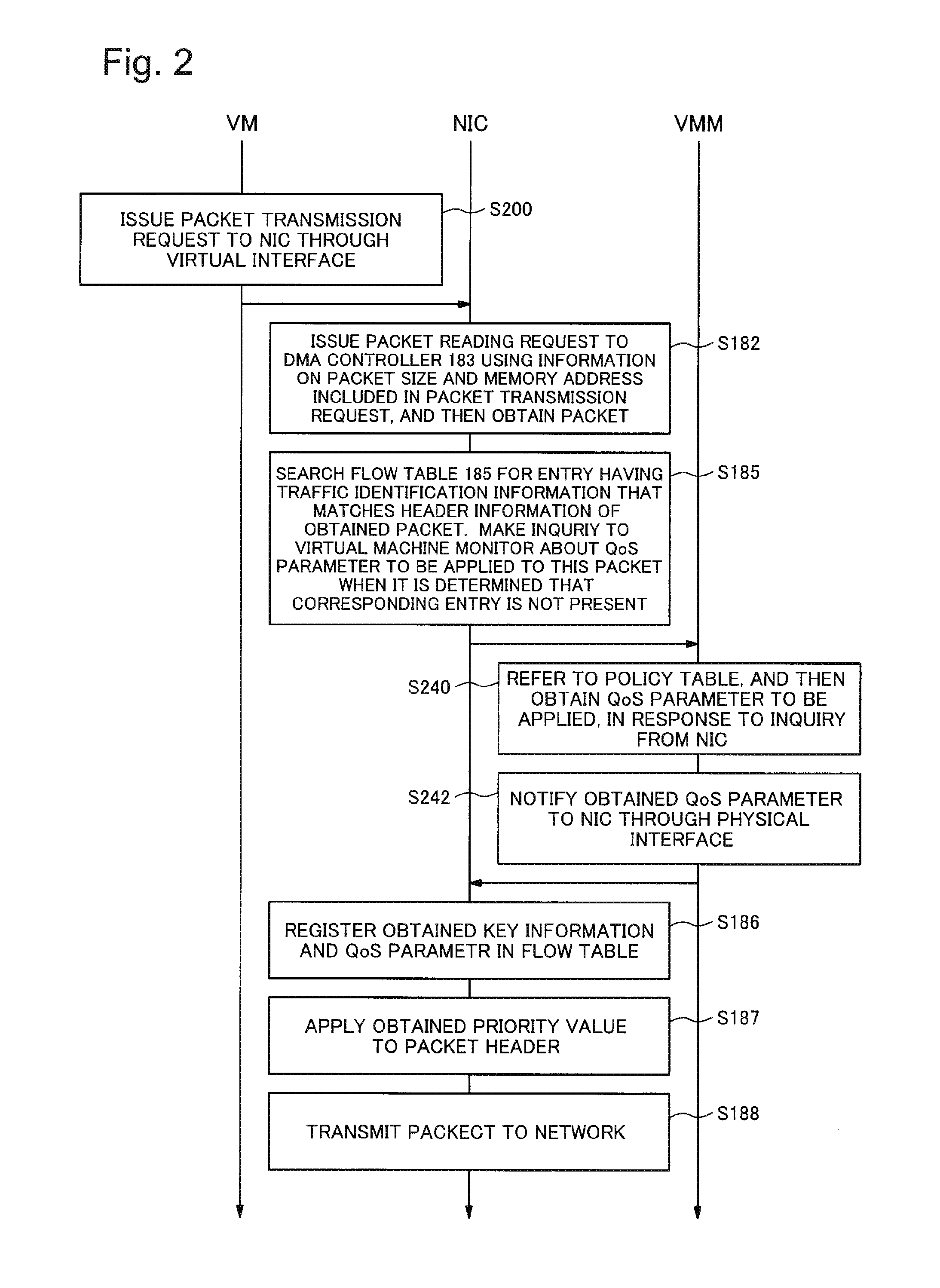
[0046]Next, a first exemplary embodiment of the present disclosure will be described in detail with reference to drawings. In the following description, a unit of data to be transferred to a network is uniformly described as a “packet”, this description does not limit the type of the network or the like to which the present disclosure is applied. Hereinafter, a series of packet sequences that is also referred to as a “flow” will be described as “traffic”. To take an example, when downloading a certain file using FTP (File Transfer Protocol), packets that have flowed from a start to completion of downloading of the certain file will be collectively described as traffic.

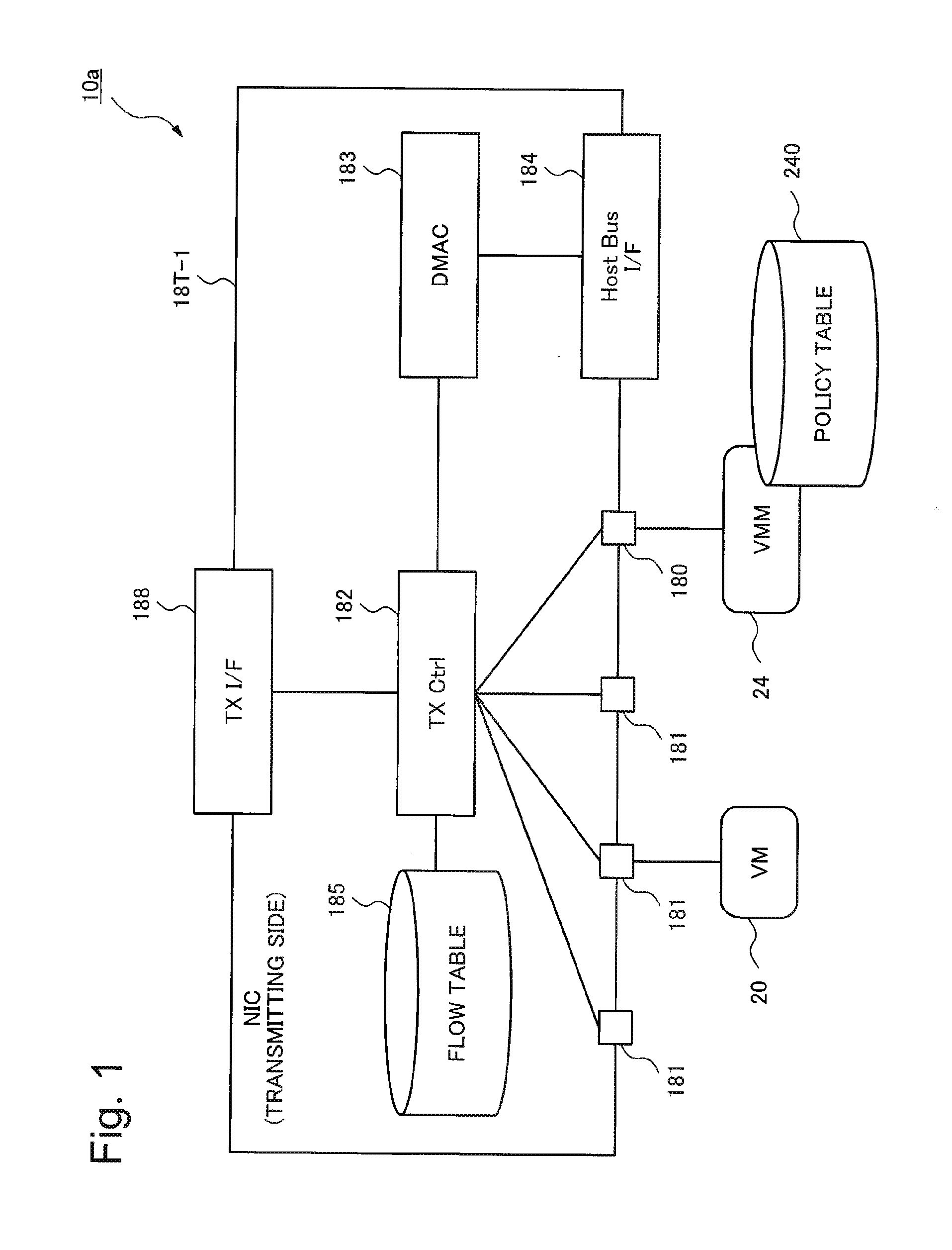
[0047]FIG. 1 is a diagram showing a configuration of a QoS control system according to the first exemplary embodiment.

Referring to FIG. 1, a QoS control system 10a including a NIC 18T-1, a virtual machine (VM) 20, and a virtual machine monitor (VMM) 24 is shown. The virtual machine 20 and the virtual machine monitor 24...

second exemplary embodiment

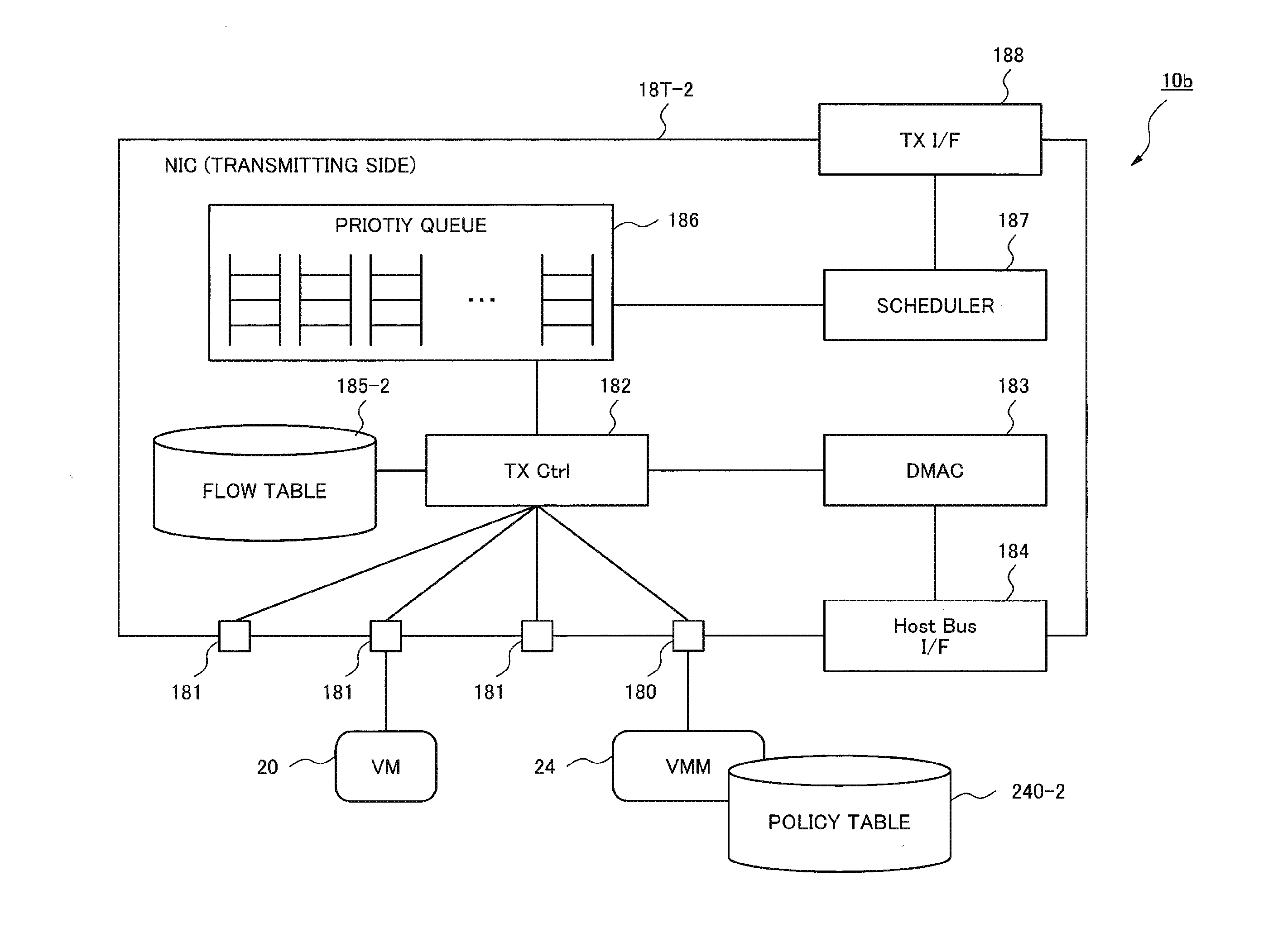
[0110]Next, a second exemplary embodiment of the present disclosure will be described in detail with reference to drawings. FIG. 6 is a diagram showing a configuration of a QoS control system 10b according to the second exemplary embodiment of the present disclosure. Referring to FIG. 6, the second exemplary embodiment of the present disclosure is the one in which a priority queue 186 and a scheduler 187 are added to the configuration in the first exemplary embodiment of the present disclosure shown in FIG. 1, and a flow table 185-2 and a policy table 240-2 are altered. Same reference signs are given to the other components that are the same as those in the first exemplary embodiment of the present disclosure, and a detailed description of the components that are the same as those in the first exemplary embodiment of the present disclosure will be omitted.

[0111]The priority queue 186 is constituted from a plurality of queues having mutually different priorities. Each queue has a dep...

third exemplary embodiment

[0142]Next, a third exemplary embodiment of the present disclosure will be described in detail with reference to drawings. FIG. 10 is a diagram showing a configuration of a QoS control system 10c according to the third exemplary embodiment of the present disclosure. Referring to FIG. 10, the configuration in which a slave policy table 242 is added to the virtual machine 20 in the configuration of the second exemplary embodiment is shown. Same reference signs are given to the other components that are the same as those in the second exemplary embodiment of the present disclosure, and a detailed description of the other components that are the same as those in the second exemplary embodiment of the present disclosure will be omitted.

[0143]A portion of entries in the policy table 240 is registered in the slave policy table 242. Specifically, when there is one of the respective queues constituting the priority queue 186 that is likely to be overflown, a policy corresponding to the prior...


PUM


Abstract

Provided is a QoS control system, a QoS control method, and a program suitable for use in a server virtualization environment in which an I / O virtualization technology can be used. The QoS control system includes a network interface and a network interface management unit. The network interface holds a QoS (Quality of Service) parameter giving identification information for identifying traffic, a priority value to be applied to a packet belonging to the traffic, and information indicating the storage location of the priority value in the packet, stores the priority value in the packet belonging to the traffic, and then transmits a resulting packet. The network interface management unit holds a QoS policy including a QoS parameter to be applied to each traffic, and manages the network interface.

Description

TECHNICAL FIELD[0001]The present invention is based upon and claims the benefit of the priority of Japanese Patent Application No. 2012-147327, filed on Jun. 29, 2012, the disclosure of which is incorporated herein in its entirety by reference thereto. The present invention relates to a QoS (Quality of Service) control system, a QoS control method, and a program. More specifically, the invention relates to a QoS control system, a QoS control method, and a program suitable for used in a server virtualization environment where an I / O virtualization technology can be used.BACKGROUND ART[0002]In recent years, due to improvement in performance and reliability of servers, introduction of virtualization of server resources (server virtualization) has been widely spread at a data center and the like. Due to a technology for the server virtualization, a service that has been operated on an individual physical server is operated on a virtual machine, and this virtual machine is held in one ph...

Claims


Application Information

Patent Timeline
Patent Type & Authority Applications(United States)
IPC IPC(8): H04L12/833H04L12/865H04L12/813H04L47/20H04L47/31H04L47/6275H04L49/111
CPCH04L47/2458H04L47/6275H04L47/20H04L47/2408
Inventor TSUJI, AKIRA
Owner NEC CORP
Why Eureka
Try Eureka