
Electric heater

Inactive Publication Date: 2015-06-04
MAHLE INT GMBH
View PDF26 Cites 2 Cited by
  • Summary
  • Abstract
  • Description
  • Claims
  • Application Information

AI Technical Summary

Benefits of technology

The present invention aims to improve the connection between the heating element and circuit board of an electric heater while minimizing mechanical stress to the heater. Additionally, the electric heater should be easy to produce.

Problems solved by technology

Therefore the mechanical stress for other connections and elements of the circuit board or the electric heater is very limited.

Method used


Image

  • Electric heater
  • Electric heater

Examples


Embodiment Construction

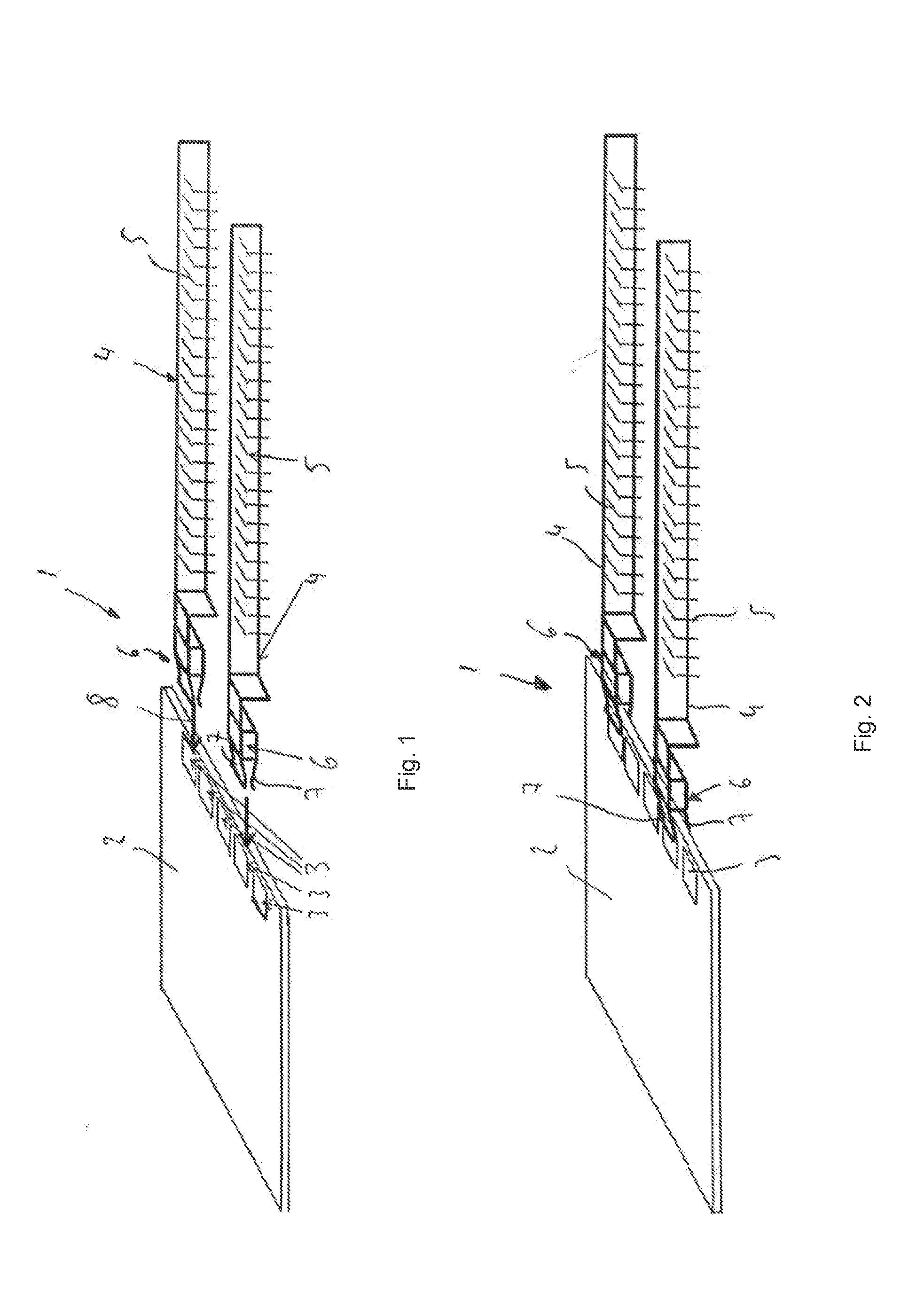
[0036]FIG. 1 shows an electric heater 1 with one circuit board 2 and two heating elements 4. Each heating element 4 possesses a multitude of heat transmitting fins 5 and at least one PTC-heating element (not shown in FIG. 1). Each heating element 4 further shows a connector clip 6, which can be used to connect the heating element 4 to the circuit board 2.

[0037]The circuit board 2 possesses a multitude of contact areas 3. These contact areas 3 are connected to a power supply that is not shown in FIG. 1. The connection between the contact areas 3 and the power supply can be realized by conducting paths and power switches on the circuit board 2. The circuit board 2 can be a printed circuit board as it is widely known in the state of the art.

[0038]The contact areas 3 are located near to one of the edges of the circuit board so that they can easily be covered by the connector clips 6 of the heating elements 4. To cover the contact areas 3 with the connecter clips 6, the connector clips 6...


PUM


Abstract

An electric heater for an automobile vehicle, with at least one heating element and with at least one circuit board, whereby the circuit board has at least one contact area through which an electrical connection between a heating element and a power supply can be realized. The heating element has at least one PTC-heating element, whereby the heating element can be clipped to the circuit board via a connector clip, and whereby the connector clip has two flexible extensions, which are arranged opposed to each other.

Description

[0001]This nonprovisional application claims priority under 35 U.S.C. §119(a) to European Patent Application No. EP13290298.2, which was filed on Dec. 3, 2013, and which is herein incorporated by reference.BACKGROUND OF THE INVENTION[0002]1. Field of the Invention[0003]The present invention relates to an electric heater for an automobile vehicle, with at least one heating element and with at least one circuit board, whereby the circuit board possesses at least one contact area through which an electrical connection between a heating element and a power supply can be realized, whereby the heating element has at least one PTC-heating element.[0004]2. Description of the Background Art[0005]Electric heaters usually have at least one heating element which can be heated by applying an electric current to the element. The heat is then transported via fins or other thermally conductive parts to a heat sink. The heat sink can thus be heated by the heating element. To control the electric cur...

Claims


Application Information

Patent Timeline
IPC IPC(8): H05B3/50H05B3/04
CPCH05B3/04H05B3/50F24H3/0429F24H3/0435F24H3/0447H05K1/117H05K2201/10386H01R12/722H05B2203/023H01R13/113H01R12/721
Inventor GRIES, JEAN-PHILIPPE
Owner MAHLE INT GMBH
Learn More