Piece of furniture and device for moving a furniture flap of a piece of furniture

a technology for furniture and furniture flaps, which is applied in the direction of wing openers, door/window fittings, constructions, etc., can solve the problem that the direct action of users on the furniture flaps is generally only possible in limited extent, and achieves the effect of convenient control

Inactive Publication Date: 2015-06-11
GRASS GMBH
View PDF2 Cites 1 Cited by
  • Summary
  • Abstract
  • Description
  • Claims
  • Application Information

AI Technical Summary

Benefits of technology

[0036]In addition, it is advantageous in this variant embodiment that the driving force for moving the furniture flap from an entirely or partially open position in a closing direction is always available by the dead weight of the furniture flap, and, in particular, a drive for moving the furniture flap itself in the closing direction is not required. It is advantageous that the closing movement, the profile thereof and beginning and end are determinable via the tension element acting on the furniture flap. When the furniture flap is open and the previously wound-up tension element is subsequently unwound, the closed position or the closing movement is then predeterminable in accordance with the unwinding length of the tension element. The value of the unwinding length of the tension element is easily controllable.
[0037]According to a further advantageous variant of the invention, guide sections acting between the furniture flap and the furniture body are provided for a predetermined opening and closing movement of the furniture flap. A defined opening or closing movement of the furniture flap relative to the furniture body is preferably reliably ensured over the entire possible movement distance. The guide sections can comprise, for example, a linear guide which is present, for example, on an end side of the furniture body. For example, the furniture flap or a section of the furniture flap can slide along the guide sections on the end side of the furniture body. In this connection, it is advantageous that a virtually wear-free, e.g. plain bearing guide is formable for the furniture flap in relation to the furniture body.

Problems solved by technology

When the furniture flap is positioned at an overhead height, a direct action of a user on the furniture flap is generally possible only to a limited extent, if at all.

Method used


Image

  • Piece of furniture and device for moving a furniture flap of a piece of furniture
  • Piece of furniture and device for moving a furniture flap of a piece of furniture

Examples


Embodiment Construction

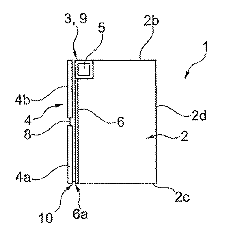
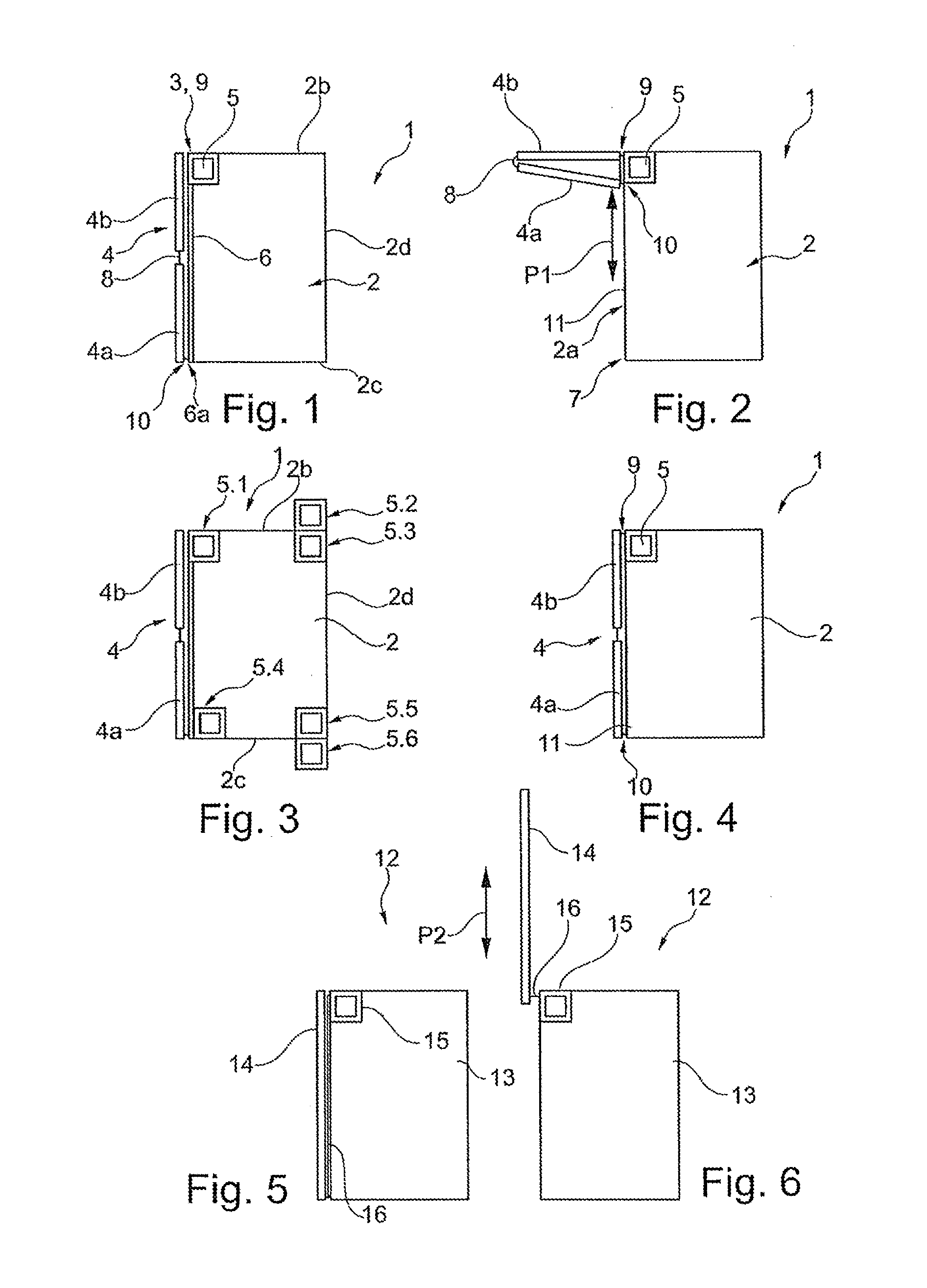
[0046]FIGS. 1 and 2 show a piece of furniture 1 comprising a furniture body 2 on which, for the temporary covering of a front side 2a, a furniture flap 4 is movably accommodated via a bearing point 3. FIG. 1 shows the completely closed furniture flap 4 and FIG. 2 shows the completely open furniture flap 4. In the installation state shown, the two-part furniture flap 4 is divided horizontally into a lower flap part 4a and an upper flap part 4b, which are connected in an articulated manner via a hinge 8.

[0047]The furniture body 2 has opposite side walls between an upper part 2b and a base 2c, and a rear wall 2d. The bearing point 3 forms a hinge 9, and therefore the upper flap part 4b is pivotable in relation to the furniture body 2 about a substantially horizontal axis close to or along a narrow end side of the upper part 2b. According to the invention, a flap fitting is not provided or necessary between the furniture body 2 and the furniture flap 4 in order to open the furniture fla...


PUM


Abstract

A device for moving a furniture flap of a piece of furniture is proposed, wherein the device has bearing means via which the furniture flap is movably accommodated on a furniture body. According to the invention, the device comprises a tension element arrangement, comprising a tension element and a drive motor for driving the tension element, in such a manner that, in the mounted state of the device, a first end of the tension element is received on a winding element and a second end of the tension element is assigned to the furniture flap, wherein the furniture flap is bringable out of a closed position relative to the furniture body into an open position by a winding-up operation of the tension element.

Description

CROSS REFERENCE TO RELATED APPLICATIONS[0001]This application is a continuation of International Application No. PCT / EP2013 / 001578 filed May 29, 2013, which designated the United States, and claims the benefit under 35 USC §119(a)-(d) of German Application No. 20 2012 005 606.9 filed Jun. 11, 2012, the entireties of which are incorporated herein by reference.FIELD OF THE INVENTION[0002]The invention relates to a piece of furniture and a device for moving a furniture flap of a piece of furniture.BACKGROUND OF THE INVENTION[0003]Pieces of furniture comprising furniture flaps and devices for moving a furniture flap of a piece of furniture, wherein the device has bearing means via which the furniture flap is movably accommodated on a furniture body, are known.[0004]When the furniture flap is positioned at an overhead height, a direct action of a user on the furniture flap is generally possible only to a limited extent, if at all. This necessitates particular requirements to be imposed o...

Claims


Application Information

Patent Timeline
Patent Type & Authority Applications(United States)
IPC IPC(8): E05F15/603E05F15/632E05F1/08E05F15/605
CPCE05F15/603E05F1/08E05F15/632E05F15/605E05D15/262E05D15/264E05Y2900/20E05Y2201/644
Inventor ERDEL, TOBIASMINTGEN, ROLF
Owner GRASS GMBH
Why Eureka
Try Eureka