
Magnetic metal extractor from drilling fluid

a magnetic metal and extractor technology, applied in the direction of magnetic separation, manufacturing tools, and borehole/well accessories, etc., can solve the problems of small metal debris, equipment through which the drilling fluid is recirculated, and can be damaged or quickly worn,

Inactive Publication Date: 2015-06-11
FLO RITE FLUIDS
View PDF2 Cites 11 Cited by
  • Summary
  • Abstract
  • Description
  • Claims
  • Application Information

AI Technical Summary

Benefits of technology

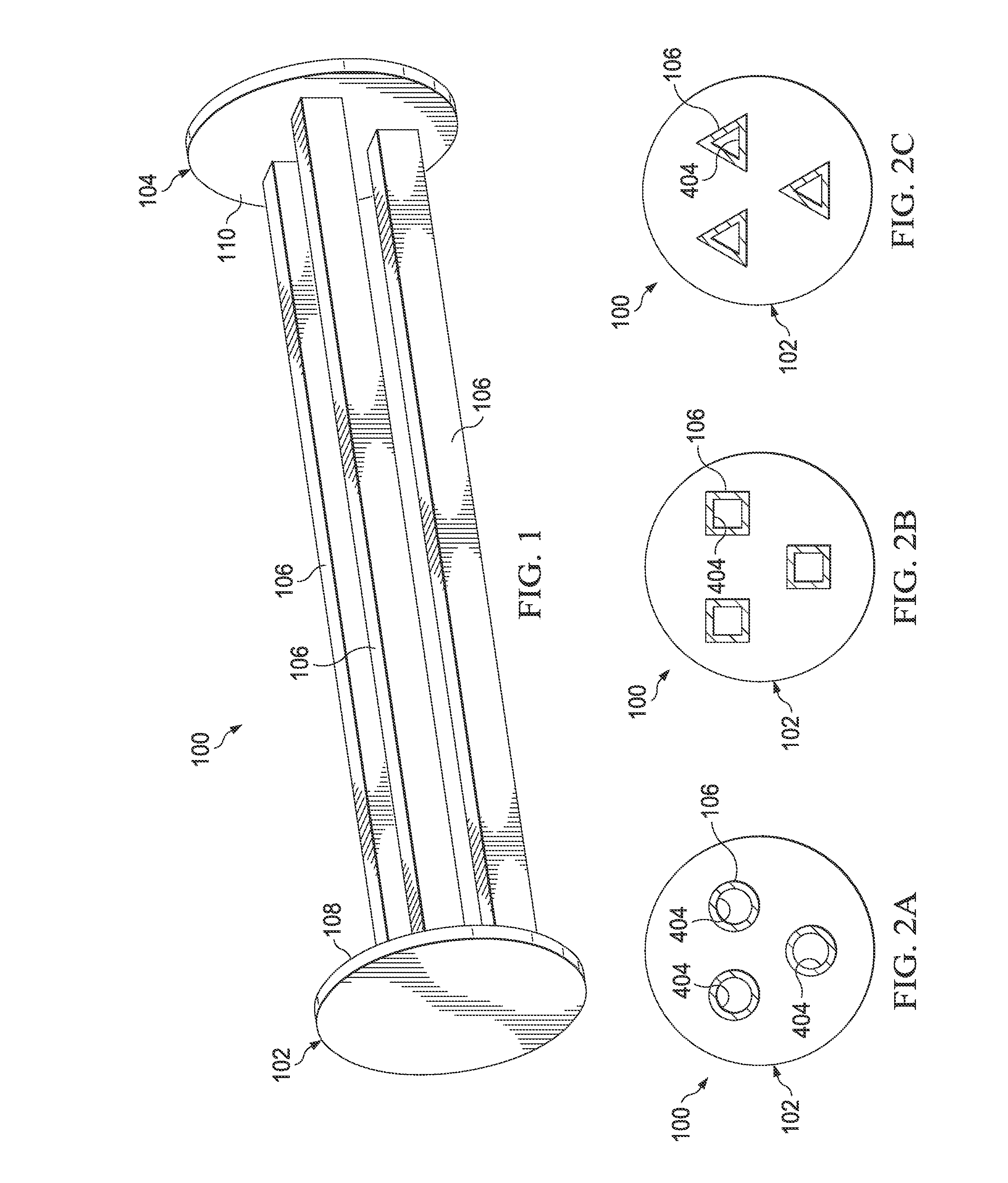
The patent describes an apparatus and method for removing metal debris from drilling fluid. The apparatus includes elongated members with magnets that can attract and remove metal debris from the drilling fluid. The elongated members may have a rectangular or triangular cross-sectional shape and may be cylindrical or movably suspended in the flow path. The interior of the elongated members may have a sealed interior channel with a catalyst or a sealed interior channel with a triplex. The method involves flowing the drilling fluid through the elongated members and using the magnets to attract and remove the metal debris. The apparatus and method can effectively remove metal debris from drilling fluid and improve the quality of the drilling fluid.

Problems solved by technology

The equipment through which the drilling fluid is recirculated, such as, for example, high pressure pumps and drill heads, can be damaged or rapidly worn if the drilling fluid includes residual debris from the wellbore.
Unfortunately, this equipment often does not remove all debris from the drilling fluid and some debris may remain in the drilling fluid as it is recirculated.
In the case of horizontal drilling, small metal debris may result if the drill string contacts the walls of the wellbore in the area of curvature of the wellbore as the wellbore transitions from a vertical wellbore to a horizontal wellbore.
Metal debris that result from these and other drilling operations are often too small to remove from the drilling fluid using traditional drilling fluid cleansing mechanisms.
Unfortunately, these small metal debris can also be very damaging to drilling equipment, such as high pressure pumps, as the used drilling fluid is recirculated.

Method used


Image

  • Magnetic metal extractor from drilling fluid
  • Magnetic metal extractor from drilling fluid
  • Magnetic metal extractor from drilling fluid

Examples


Embodiment Construction

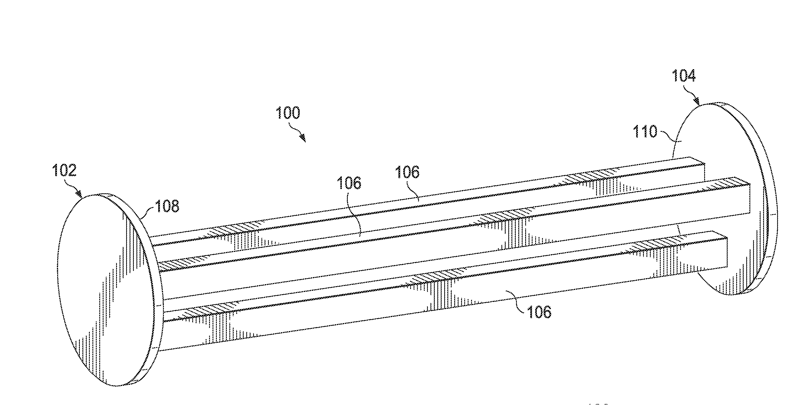
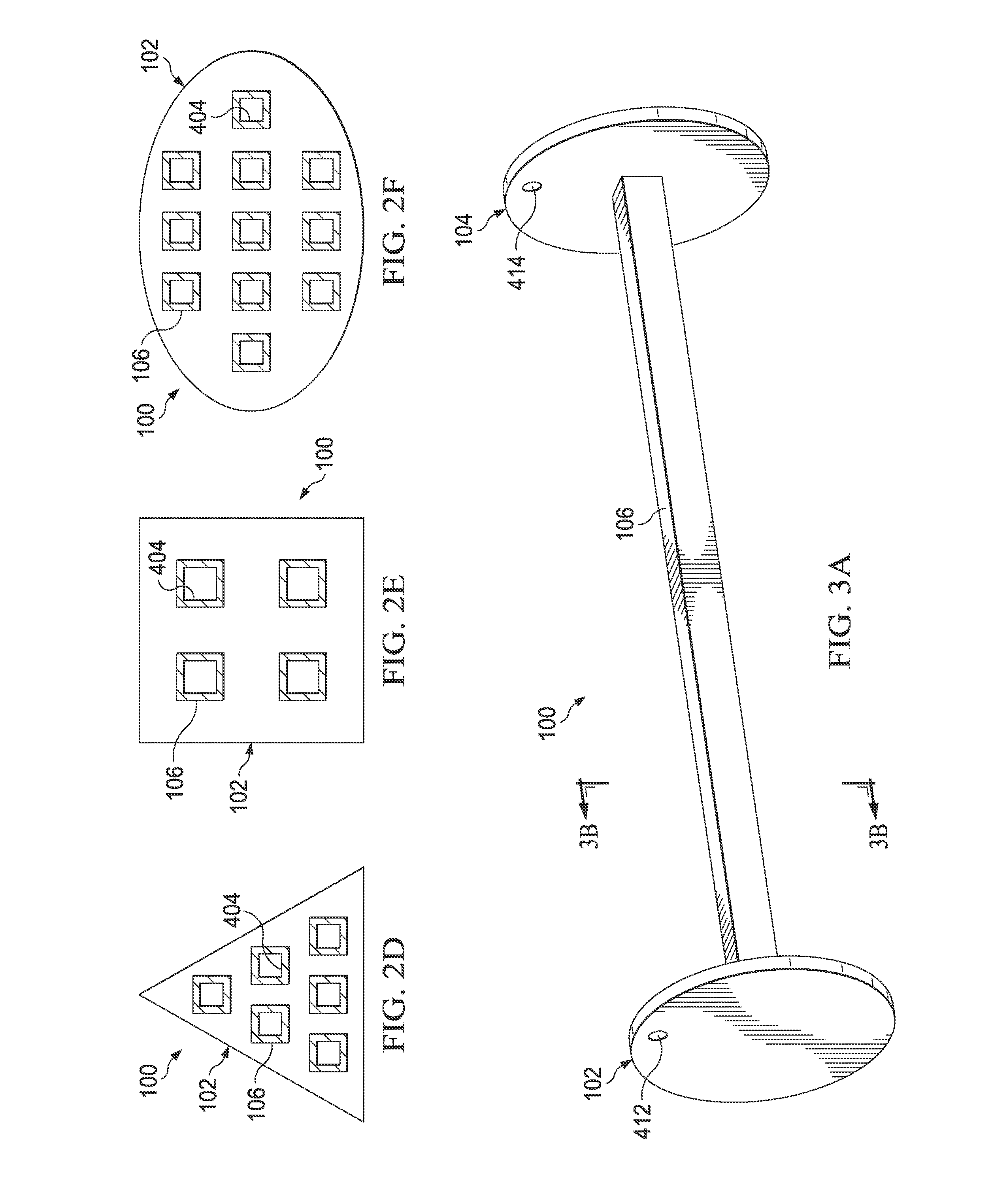
[0071]FIG. 1 is a perspective, front view of an embodiment of an apparatus 100 for removing metallic debris from a drilling fluid. The apparatus 100 may include a first end member 102, a second end member 104 spaced from the first end member 102, and one or more elongated members 106 extending between the first end member 102 and the second end member 104. As will be described in more detail below, the elongated members 106 may include one or more magnets 402 (see, e.g., FIGS. 3C, 5C and 8) or may otherwise exert a magnetic force to attract metallic debris from a drilling fluid that passes by the apparatus 100.

[0072]In some embodiments, the first and second end members 102 and 104 are located in a spaced apart relationship to allow drilling fluid to pass therebetween. As will be explained in more detail below, a distance between the end members 102 and 104 may be slightly less than the width of an outlet of a drilling fluid cleansing apparatus (see e.g., outlet 606 of drilling fluid...


PUM

PropertyMeasurementUnit
diameteraaaaaaaaaa
thickaaaaaaaaaa
widthaaaaaaaaaa

Abstract

An exemplary apparatus for removing metallic debris from a drilling fluid is provided that includes a first end member, a second end member, and one or more elongated members extending between the first end member and the second end member. The elongated members may each include at least one magnet. Drilling fluid may flow past the elongated members, which may be located in a drilling fluid cleansing machine such as a shale shaker, so that metallic debris in the drilling fluid, if any exist, are attracted by the magnets in the elongated members. Some of the metallic debris may adhere to an exterior surface of the elongated members so that the metallic debris are removed from the drilling fluid. The metallic debris can then be removed from the exterior surface of the elongated members.

Description

CROSS-REFERENCE TO RELATED APPLICATIONS[0001]Pursuant to 35 U.S.C. §119(e), this application claims priority from, and hereby incorporates by reference for all purposes, U.S. Provisional Patent Application Ser. No. 61 / 914,311, entitled “Magnetic Metal Extractor From Drilling Fluid,” filed Dec. 10, 2013 and naming John W. White as an inventor.TECHNICAL FIELD[0002]This disclosure relates in general to removing debris from drilling fluid and, in particular, but not by way of limitation, to extracting metal debris from drilling fluid.BACKGROUND OF THE DISCLOSURE[0003]Drilling fluid, also known as “drilling mud,” is used in oil and gas drilling operations to perform many tasks, such as cooling and lubricating equipment and removing debris from the wellbore. In a drilling operation, drilling fluid is pumped into the wellbore where it collects debris and cools and lubricates equipment, such as the drill head. Then, the drilling fluid is recirculated to the top of the wellbore to carry debr...

Claims


Application Information

Patent Timeline
Patent Type & Authority Applications(United States)
IPC IPC(8): E21B21/01
CPCE21B2021/007E21B21/01E21B21/065Y10T29/49826B03C1/286B03C1/0332B03C2201/28
Inventor WHITE, JOHN W.
Owner FLO RITE FLUIDS
Learn More