
Air control system with an integrated diagnostic device for a motor vehicle

a technology of air control system and diagnostic element, which is applied in the direction of roofs, doors, instruments, etc., can solve the problems of increasing assembly cost and susceptibility to failure, increasing the high cost of air control system, so as to reduce the rotational speed of motors that function as power units and preserve power and limits.

Active Publication Date: 2015-06-11
ROECHLING AUTOMOTIVE SE & CO KG
View PDF6 Cites 22 Cited by
  • Summary
  • Abstract
  • Description
  • Claims
  • Application Information

AI Technical Summary

Benefits of technology

This patent describes an air control system that uses a resistance element, which is a simple and low-cost component that does not need to be supplied with energy. The system uses different phases to control the air conditioning, making it easier to switch between different elements. The use of a motor with reduced speed also helps to achieve a soft and controlled approach to the closed position while maintaining power and limits. Overall, the system is cost-effective, efficient, and easy to use.

Problems solved by technology

Such sensors require construction space, must be supplied with energy, and increase the assembly cost as well as the susceptibility to failure and, not least, increase the cost of the air control system.
In order to check whether such an air control system is functioning properly, namely whether all air flaps displace according to the control commands, it is not sufficient to check the position of the power unit, but moreover the status of each individual air flap must be acquired by a special sensor, which for the reasons previously stated, makes the air control system technically complicated, prone to error, and expensive

Method used


Image

  • Air control system with an integrated diagnostic device for a motor vehicle
  • Air control system with an integrated diagnostic device for a motor vehicle
  • Air control system with an integrated diagnostic device for a motor vehicle

Examples


Embodiment Construction

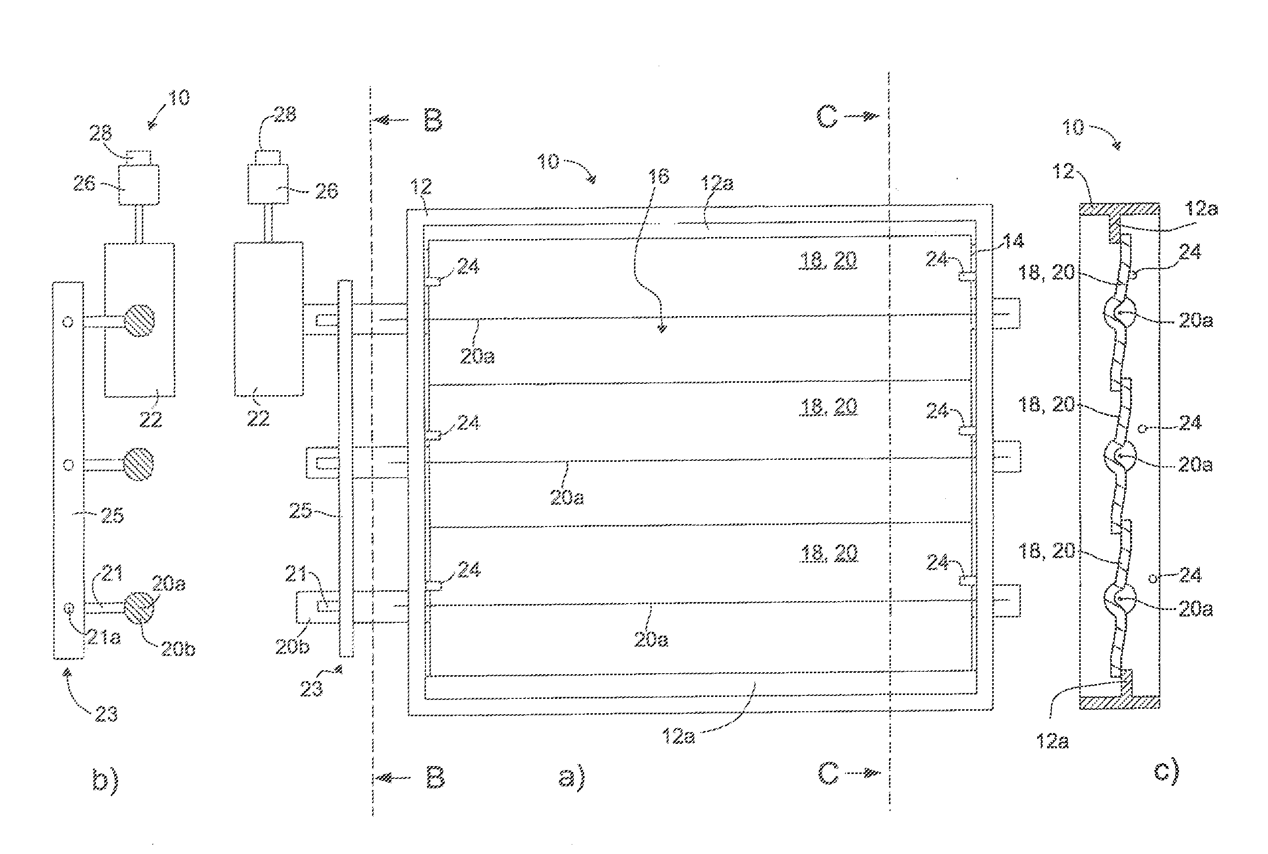
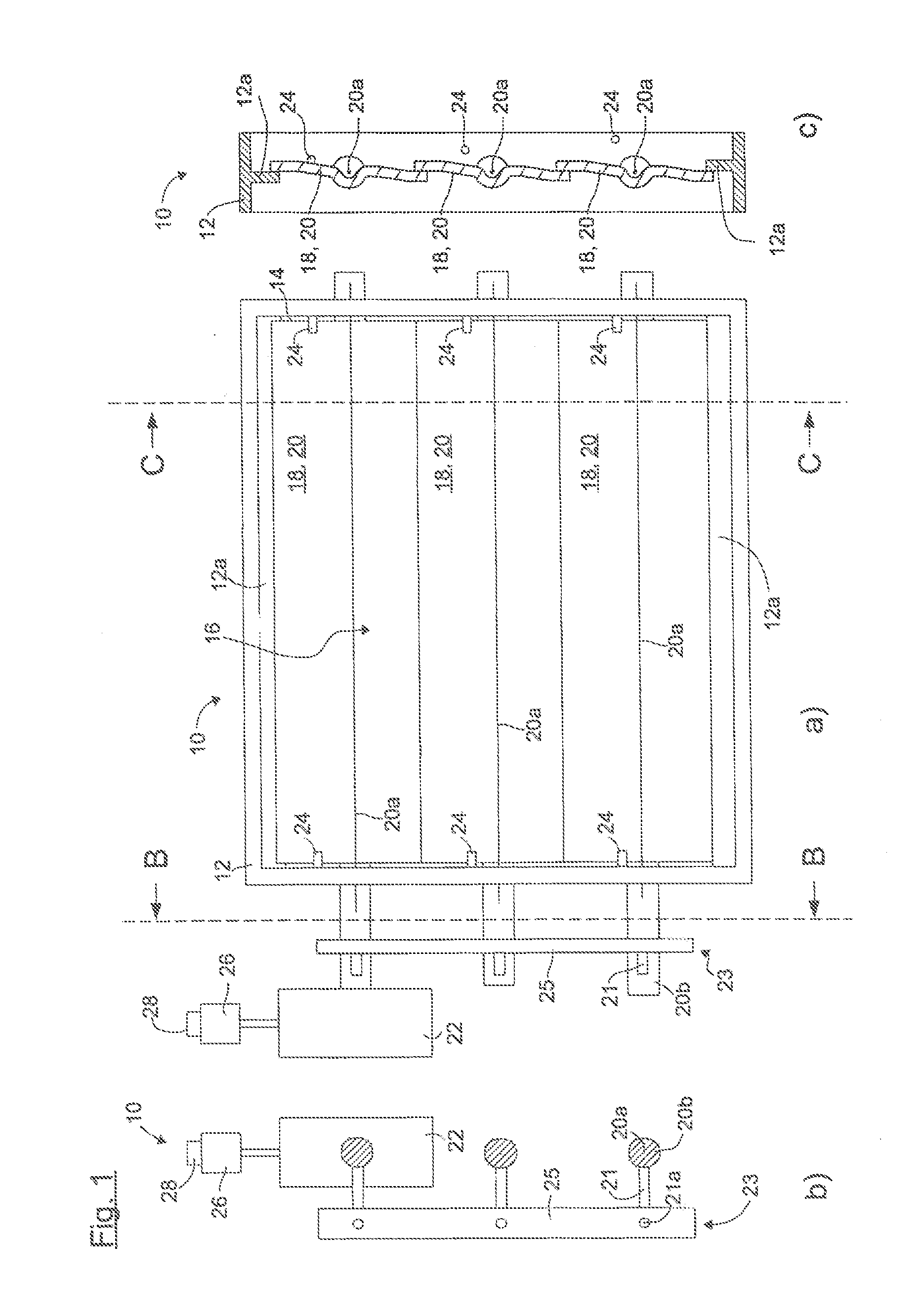
[0048]FIG. 1a) shows a view of the back side of a first embodiment of an inventive air control system 10.

[0049]The front side opposite the depicted back side is thereby that side of the air control system with inlet air flow during the operation of the vehicle, if the air control system 10 is built into the vehicle. When inserted into a radiator grill, the back side depicted in FIG. 1a) is that side which in a built-in state faces the interior of a vehicle, which is not shown in the figures.

[0050]The air control system 10 encompasses, as FIG. 1a) shows, a carrier structure 12 and an air output opening 14 whose flow cross-section can be varied by an adjustable closing element arrangement 16 positioned on the carrier structure 12.

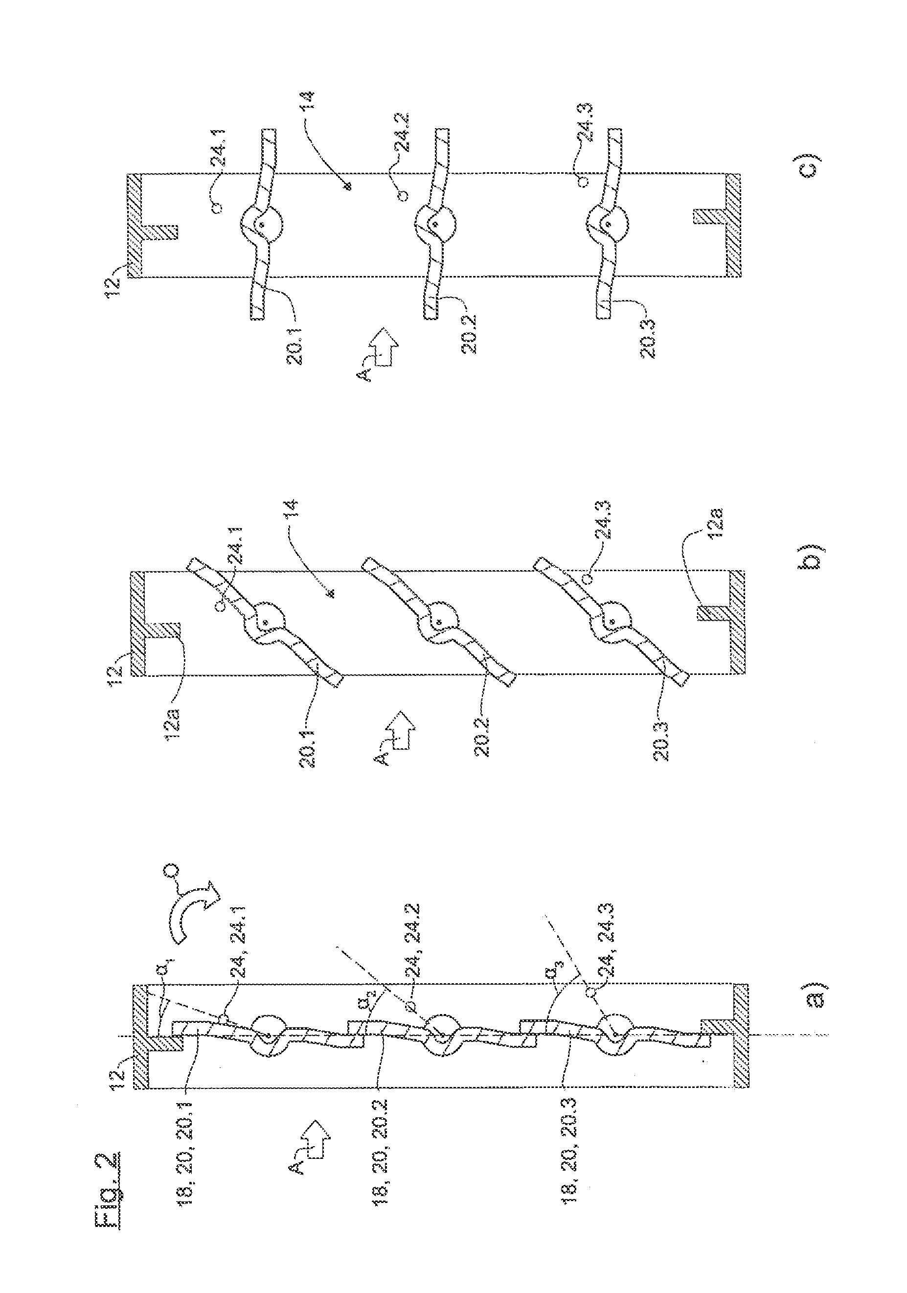
[0051]In the example shown, this includes three closing elements 18, which here involves air flaps 20 that can be mounted to pivot around the flap axis 20a on the carrier structure 12.

[0052]The adjustment movement of the closing elements 18 is powered by an a...


PUM


Abstract

An air control system with an integrated diagnostic device for a motor vehicle includes: a carrier structure, an air output opening, a closing element arrangement with one or several closing elements adjustably placed on the carrier structure a power unit which is constructed to adjust the closing element arrangement in an adjustment movement, a diagnostic device to acquire information about the condition of the closing element arrangement, an interface to convey data at least from the diagnostic device to another device, wherein for at least one closing element of the closing element arrangement the air control system also includes a resistance element associated with said closing element which is constructed to temporarily change the torque or force required in a predetermined phase of the adjustment movement for the adjustment of the closing element arrangement, wherein the diagnostic device acquires at least one operating parameter of the power unit as information about the status of the closing element arrangement.

Description

CROSS REFERENCE TO RELATED APPLICATIONS)[0001]This application claims priority to German Application No. 10 2013 225 629.9, filed Dec. 11, 2013. The entirety of the disclosure of the above-referenced application is incorporated herein by reference.BACKGROUND OF THE INVENTION[0002]1. Field of the invention[0003]The present invention relates to an air control system with an integrated diagnostic element for a motor vehicle, including a carrier structure; an air output opening; a closing element arrangement adjustably mounted on the carrier structure for variation of the flow cross-section of the air output opening at least between a closed position and an open position with one or several closing elements; a power unit that is constructed to adjust the closing element arrangement in an adjusting motion at least between the closed position and the open position; a diagnostic device that is constructed to acquire information about the status of the closing element arrangement; and an in...

Claims


Application Information

Patent Timeline
IPC IPC(8): F01P11/14B60K11/08
CPCB60K11/085F01P11/14B60Y2306/15Y02T10/88Y10T74/1892B60K11/04B60K11/08B60J5/0493B60J7/0573B60J7/22E05Y2400/508E05Y2400/554E05F15/41E05F15/603E05F15/40E05F15/443E05F15/695F01P7/10
Inventor SOLAZZO, DOMENICO
Owner ROECHLING AUTOMOTIVE SE & CO KG
Learn More