Steering Column Assembly

a technology for steering columns and assemblies, applied in steering parts, vehicle components, transportation and packaging, etc., can solve the problems of affecting the adjustment of the steering column, the weight of the steering column and the driver's lap, and the steering wheel and shroud could fall into the driver's lap with considerable force, so as to reduce the friction, reduce the friction, and reduce the friction

Active Publication Date: 2015-06-18
TRW LIMITED
View PDF9 Cites 1 Cited by
  • Summary
  • Abstract
  • Description
  • Claims
  • Application Information

AI Technical Summary

Benefits of technology

[0009]The cylindrical roller, which may be considered to be a wheel, may be arranged so that the inner face of the cylindrical roller and axle form a plain bearing whereby the roller may directly engage the axle surface, and slide relative to the axle face as the shroud is adjusted and the roller turns around the axle. Bearings may be provided between the axle and roller, and optionally a bushing may be provided between the axle and the roller. The applicant has appreciated that adjustment does not happen often and so wear is not an issue, and the friction present is relatively low compared with other forces the resist reach adjustment of the shroud, so a simple plain bearing may be the preferred arrangement for many embodiments.
[0010]At any given point on the roller the distance between the outer surface and the inner surface of the roller that engages the axle may be at least twice the outer diameter of the axle, and preferably at least 3 times the diameter or perhaps more than 4 times the diameter. The applicant has appreciated that the larger this distance (which will be the radius for a cylindrical roller) on the roller relative to the axle the lower the friction and the lower the force required to turn the roller. The applicant has appreciated that reduced force is advantageous because it reduces the force required to move the shroud telescopically.

Problems solved by technology

If the clamp mechanism is released and some additional support of the shroud is not present the steering wheel and shroud could fall down into a drivers lap with considerable force.
Also, the weight of the assembly may inconvenience the driver when raising the wheel to the required position and securing the clamp mechanism.
As the driver typically needs one hand free to operate the clamp this adjustment may prove burdensome.
This movement can be quite stiff if friction is high and the operation may be noisy.

Method used


Image

  • Steering Column Assembly
  • Steering Column Assembly
  • Steering Column Assembly

Examples


Embodiment Construction

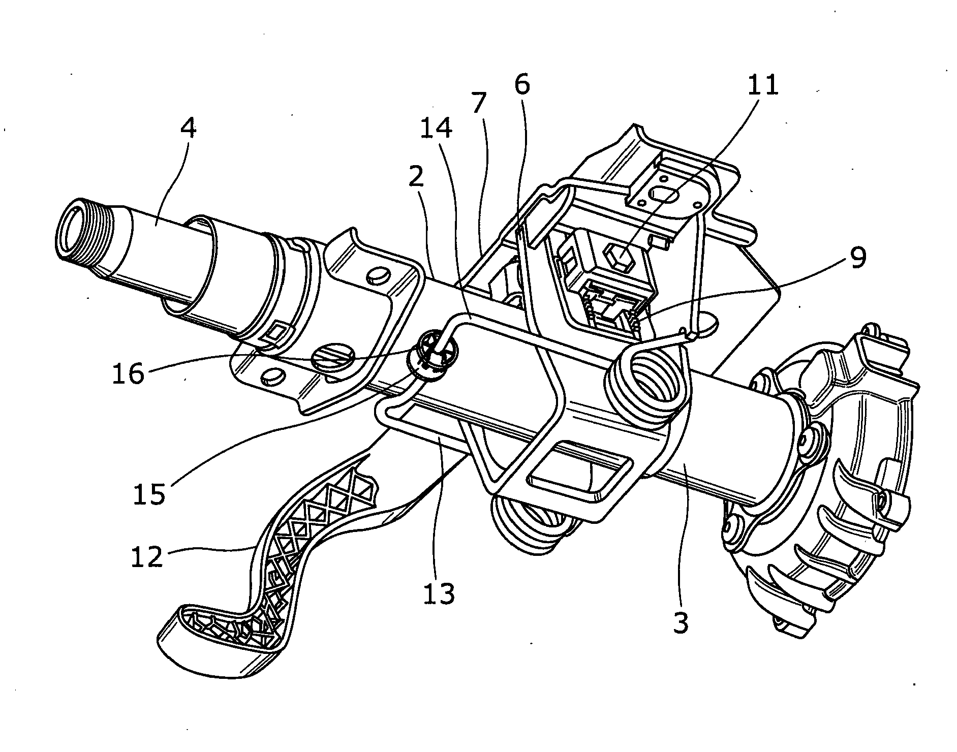
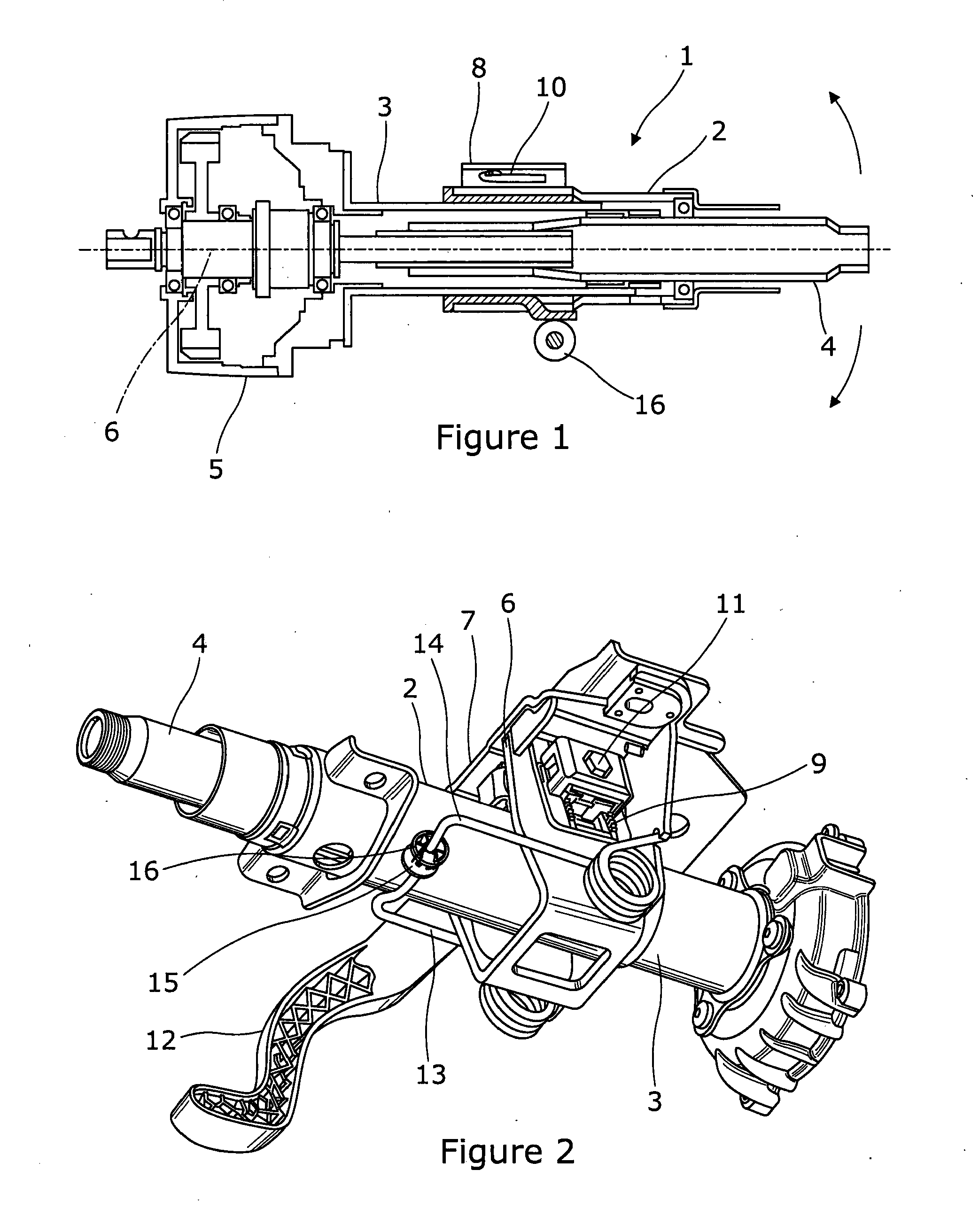
[0026]A steering column assembly 1 is shown in FIGS. 1 and 2 of the accompanying drawings. The assembly comprises a telescopic shroud having an upper axially movable part 2 and a lower axially fixed part 3. The upper and lower parts are generally tubular with an upper end of the lower part fitted inside a lower end of the upper part. The lower part is fixed to the vehicle (not shown) by a pivot. A steering shaft 4 is supported in bearings journaled to the inside of the shroud, a steering wheel 5 is connected to an upper end of the shaft 4, and an optional electric power assisted steering gearbox 5 is connected to the end of the steering shaft 4 furthest from the steering wheel. The gearbox 5 connects the shaft 4 to a motor which provides assistance when the driver tries to turn the wheel by applying a torque of the same sense as that applied by the driver. The gearbox also connects the shaft through further mechanical links such as a steering rack to the road wheels (not shown) in a...


PUM


Abstract

A steering column assembly for a vehicle, comprises a shroud comprising an axially movable upper portion and an axially fixed lower portion, which move telescopically to provide adjustment for reach of the steering column assembly, a steering shaft supported by the shroud, a pivot which connects a part of the lower portion to a fixed part of the vehicle, a clamp mechanism which releasably fixes the upper and lower portions and the shroud in position relative to a further fixed part of the vehicle. A sprung support assembly is secured to a fixed part of the vehicle and includes an axle that passes underneath the upper portion of the shroud and a cylindrical roller that surrounds a part of the axle and has an outer surface that engages the underside of the shroud and an inner surface that bears on the axle, the sprung support at least partially supports the weight of the shroud when the clamp mechanism is released, and the cylindrical roller rotating around the axle as the shroud is adjusted for reach.

Description

CROSS-REFERENCE TO RELATED APPLICATIONS[0001]This application is a national stage of International Application No. PCT / GB2013 / 051267 filed May 16, 2013, the disclosures of which are incorporated herein by reference in entirety, and which claimed priority to Great Britain Patent Application No. 1208791.2 filed May 18, 2012, the disclosures of which are incorporated herein by reference in entirety.BACKGROUND OF THE INVENTION[0002]This invention relates to improvements in steering column assemblies for vehicles.[0003]It is known to provide a steering column assembly in which the steering shaft is adjustable for steering wheel height known as reach and for steering wheel distance known as rake. Such assemblies are known as double adjust steering columns. A steering column shroud is provided that supports the steering shaft that in turn supports the steering wheel. The shroud is in two parts, an upper part and a lower part, with the upper part telescoping over or into the lower part to p...

Claims


Application Information

Patent Timeline
Patent Type & Authority Applications(United States)
IPC IPC(8): B62D1/189
CPCB62D1/189B62D1/184B62D1/185
Inventor DAVIES, NICLASWILKES, MARK ANTHONY
Owner TRW LIMITED
Why Eureka
Try Eureka