Eureka AIR delivers breakthrough ideas for toughest innovation challenges, trusted by R&D personnel around the world.

Completion Systems With a Bi-Directional Telemetry System

Active Publication Date: 2015-06-18
BAKER HUGHES INC
View PDF2 Cites 27 Cited by
  • Summary
  • Abstract
  • Description
  • Claims
  • Application Information

AI Technical Summary

Benefits of technology

[0008]Examples of the more important features of a well treatment system and methods that have been summarized rather broadly in order that the detailed description thereof that follows may be better u

Problems solved by technology

Other formations possess low mobility and the hydrocarbons trapped therein are unable to move with ease from the reservoir into the well.
However, commercially utilized inner

Method used


Image

  • Completion Systems With a Bi-Directional Telemetry System
  • Completion Systems With a Bi-Directional Telemetry System
  • Completion Systems With a Bi-Directional Telemetry System

Examples


Example

DETAILED DESCRIPTION OF THE DRAWINGS

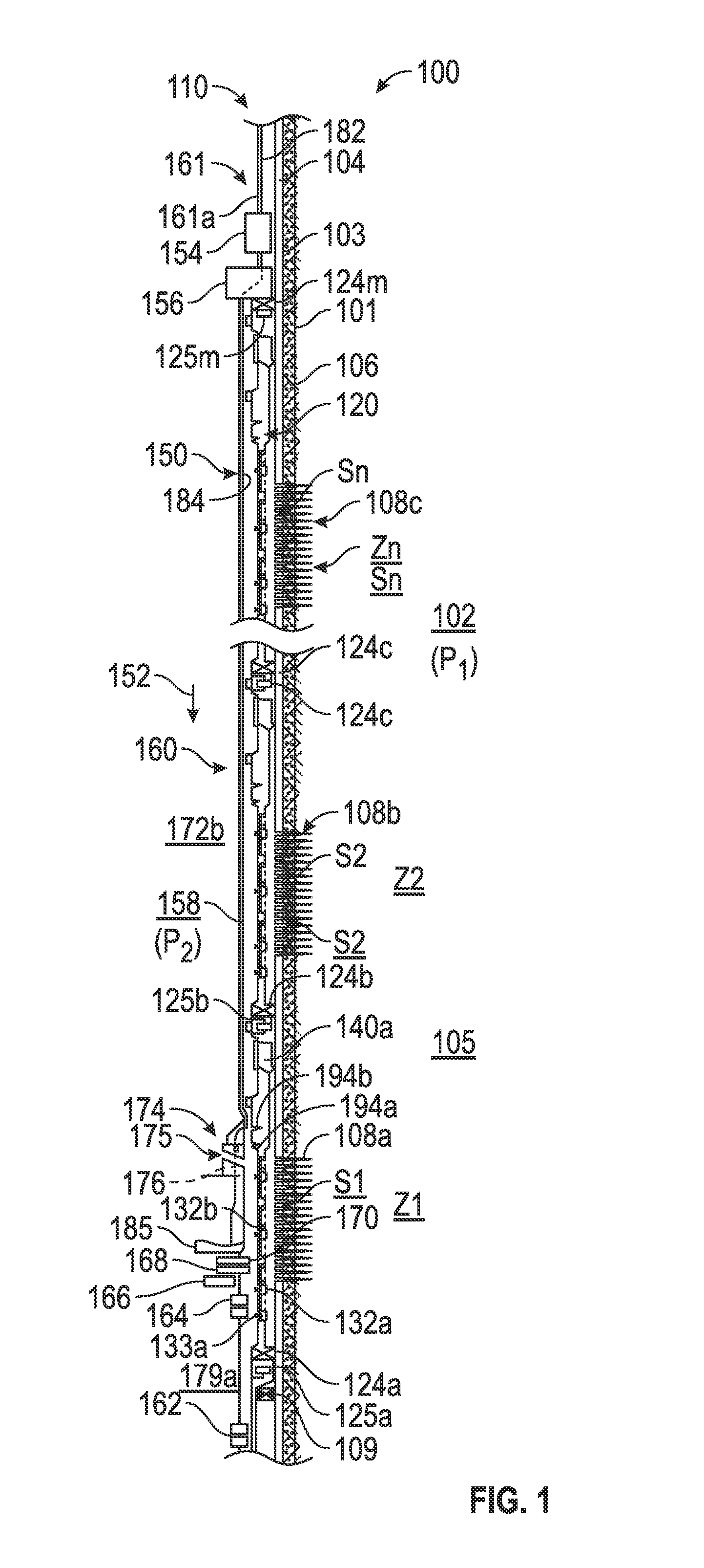
[0016]FIG. 1 is a line diagram of a section of an exemplary multi-zone wellbore system 100 that is shown to include a wellbore 101 formed in formation 102 for performing a treatment operation therein, such as fracturing the formation (also referred to herein as fracing or fracking), frac-packing, gravel packing, etc. and for determining, in real time or near real time, parameters of interest relating to such operations from sensors deployed in the system 100 and taking actions in response to such determined parameters of interest. The wellbore 101 is lined with a casing 104, such as a string of jointed metal pipe sections, known in the art. The space or annulus 103 between the casing 104 and the wellbore 101 is filled with cement 106. The system 100 is described herein in reference to a cased-hole; however, the concepts, apparatus and methods as described herein or with obvious modifications may equally be utilized for open holes. The particular e...


PUM


Abstract

An apparatus for use in a wellbore for performing a treatment operation is disclosed that in one non-limiting embodiment may include an inner string that further includes a first tubular having a first communication link, and a service tool including a cross-over tool having a fluid flow passage therein for supplying a treatment fluid under pressure from an inside of the service tool to an outside of the service tool, and wherein the service tool includes a second communication link operatively coupled to the first communication link and wherein the second communication link runs across or through the fluid flow passage in the cross-over tool that is protected from direct flow of the fluid under pressure from the inside of the service tool to the outside of the service tool.

Description

BACKGROUND[0001]1. Field of the Disclosure[0002]This disclosure relates generally to apparatus and methods for completing a wellbore for the production of hydrocarbons from subsurface formations, including fracturing, gravel packing and flooding selected zones and for communicating information in real-time about various downhole operations.[0003]2. Background of the Art[0004]Wellbores are drilled in subsurface formations for the production of hydrocarbons (oil and gas). Modern wells can extend to great well depths, often more than 6000 meters (about 20,000 ft.). Hydrocarbons are trapped in various traps in the subsurface formations at different depths. Such sections of the formation are referred to as reservoirs or hydrocarbon-bearing formations or zones. Some formations have high mobility, a measure of the ease of the hydrocarbons flow from the reservoir into a well drilled through the reservoir under natural downhole pressures. Other formations possess low mobility and the hydroca...

Claims


Application Information

Patent Timeline
IPC IPC(8): E21B34/06E21B47/00E21B47/01E21B43/26E21B47/14E21B47/06E21B49/08
CPCE21B34/06E21B47/06E21B47/065E21B47/011E21B49/08E21B43/26E21B47/14E21B47/0002E21B47/12E21B47/002E21B47/07E21B2200/06E21B47/0025E21B17/003E21B23/06E21B43/045E21B43/08E21B43/14E21B47/16
Inventor HAMMER, AARON C.O'BRIEN, ROBERT S.
Owner BAKER HUGHES INC
Why Eureka
Eureka Blog
Learn More