
Self-centering mechanism, a clamping device for an electronic device and means for their integration

Active Publication Date: 2015-06-18
CARSON OPTICAL
View PDF56 Cites 22 Cited by
  • Summary
  • Abstract
  • Description
  • Claims
  • Application Information

AI Technical Summary

Benefits of technology

The present invention is an improved self-centering mechanism for objects and a clamping device for retaining electronic devices. The mechanism is biased for easy engagement with objects of different sizes and shapes. The clamping device is easy to use and intuitive. The method and apparatus are also provided.

Problems solved by technology

Furthermore, most of the self-centering mechanisms lack an easy and intuitive means to actuate the self-centering clamp, especially with a low hand force required compared to the amount of clamping force applied.
Yet, many clamping devices for electronic devices are specific to the device, and cannot account for various differences in the electronic device, such as when the electronic device is within a case of various geometries.
There are several approaches that retain an electronic device over a range of sizes, but each method has deficiencies in ease of use, compact size, repeated usage and integration with other devices for mounting or alignment applications.
This method is awkward for the user, typically requires two hands and can inconsistently clamp the electronic devices within the specified size range.
The tacky or sticky member can be made from a selection of materials; however, the adhesion properties of these materials have a limited lifetime, or must be refreshed with water or another material.
The adhesive nature also makes the device attract dust and dirt, and requires a lot of user maintenance.
The X-shaped clamp remedies some of the previous prior art deficiencies, however, such a device still has several disadvantages.
In terms of the use, such an approach could be difficult for the user to clamp their phone as it requires pulling apart two biased opposing arms.
Also, it's centralized and thick mechanism does not allow for easy integration with some other devices, for example, but not limited to, a large optical element connected to the camera of the electronic device.
Furthermore, this approach does not lend itself to an easy or integrated means of alignment.
For example, if the device needed to be aligned to another device or mechanism, this device would have to include additional mechanisms to make an adjustment to the alignment in at least two directions, thereby making the final device overcomplicated and bulky.
Limited prior art examples exist for such a self-centering adapter device for an electronic device.
The obvious combination of known devices provides for an adapter, but does not overcome any of the known disadvantages with each individual device.
The second prior art reference also does not include any bias means, such that all clamping must be done manually and are time-consuming as a result.
No prior art exists for a compact and portable optical adapter which integrates a novel self-centering mechanism and clamping device for an electronic device.

Method used


Image

  • Self-centering mechanism, a clamping device for an electronic device and means for their integration
  • Self-centering mechanism, a clamping device for an electronic device and means for their integration
  • Self-centering mechanism, a clamping device for an electronic device and means for their integration

Examples


first embodiment

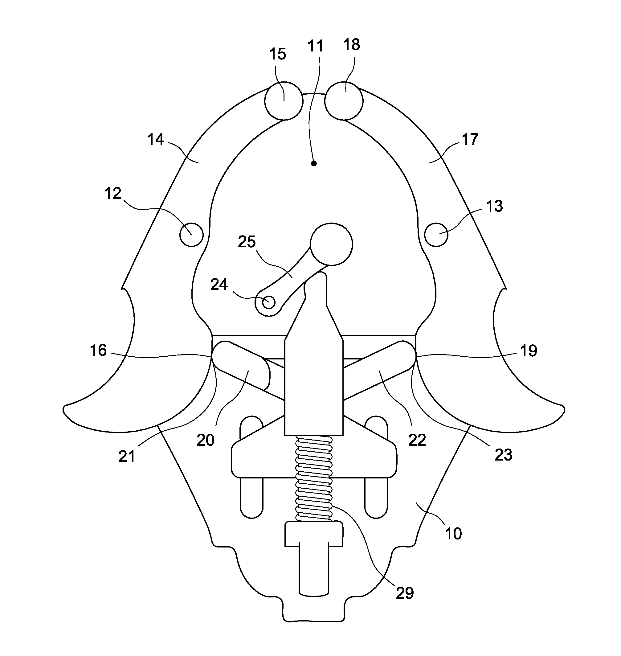
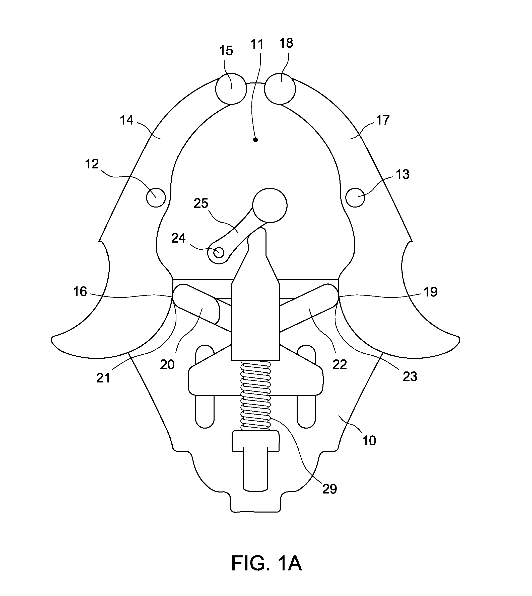
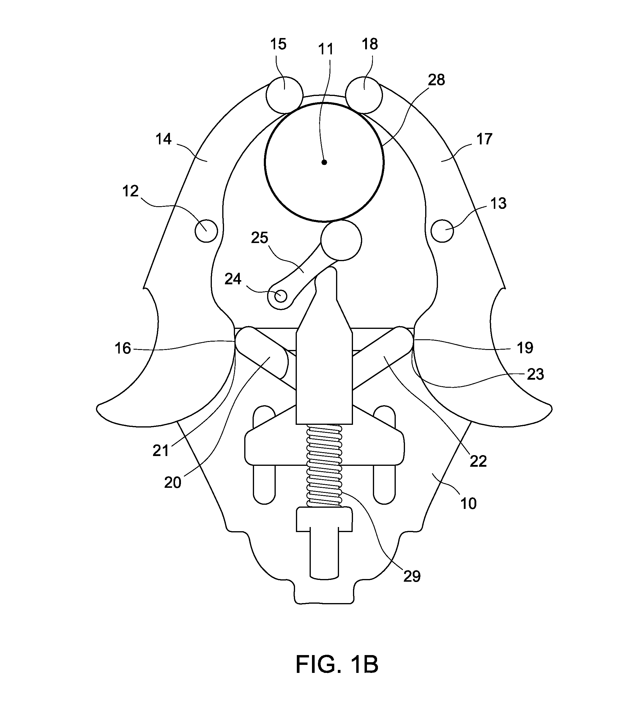
[0066]The first preferred embodiment of the self-centering mechanism depicted in FIG. 1A, depicts the first arm (14) and second arm (17) rotateably coupled to the main body at their respective pivot axes (12, 13). The third arm (25) also is rotateably coupled to the main body at a third pivot axis (24). The first and second tangential members (20, 22) move tangentially with the tangential member of the first arm (16) and the tangential member of the second arm (19). In this embodiment of the self-centering mechanism, the tangential movement is accomplished via tangential contact between the respective sets of surfaces (16 and 21, 19 and 23). The third arm is coupled to the first and second tangential member by an intermediate member. In this first embodiment of the self-centering mechanism, the intermediate member couples to the third arm by another tangential contact between surfaces. However, this coupling could also be achieved by various methods, such as but not limited to: mech...

fourth embodiment

[0079]A fourth preferred embodiment of the clamping device FIG. 11A-C allows for the positioning of the electronic device in a second direction beyond the second preferred embodiment by utilizing a third holder portion 51 with a first surface of the third holder portion 52 making partial contact with at least one side of the electronic device or case. Any additional holders could be of various geometries, including but not limited to, a straight holder like the second holder, a cylindrical holder, or a corner holder, or a curved U- or V-shaped holder or any combination thereof. In this embodiment, the user just retracts the first holder portion using the lever, then can either slide the electronic device down into or place it on the clamping device, such that the second and third portions make at least partial contact with the electronic device or case, then releases so the first holder portion retains the electronic device. The fourth embodiment is an example of a device that fits ...


PUM

PropertyMeasurementUnit
Weightaaaaaaaaaa
Forceaaaaaaaaaa
Lengthaaaaaaaaaa

Abstract

This invention comprises a self-centering mechanism for retaining an object, a clamping device for retaining an electronic device or an electronic device in a case, and means to integrate the devices in an adapter form. The structure of the self-centering mechanism allows for a compact device that is capable of fitting a wide range of differently sized and shaped objects. The clamping device allows for means to retain an electronic device or an electronic device in a case that is capable of fitting a wide range of differently sized and shaped electronic device. The self-centering mechanism and clamping device can also be integrated into the form of an adapter for various applications.

Description

BACKGROUND OF THE INVENTION[0001]The present invention relates generally to a self-centering mechanism, a clamping device to retain an electronic device, and means for their integration in the form of an adapter. In particular, the present invention is directed to a self-centering mechanism and a clamping device to retain an electronic device, which each by its construction and assembly provides for significant advantages over other approaches currently available. Furthermore, the present invention is also directed to the means to integrate a self-centering mechanism with a clamping device to retain an electronic device, whereby the overall device is an adapter.[0002]Self-centering of circular, cylindrical, square or any object with at least one symmetrical cross-section is a useful feature when aligning any object to a device with an alignment axis. Self-centering mechanisms are advantageous in numerous applications, such as but not limited to, optics mounts, tool holders, work hol...

Claims


Application Information

Patent Timeline
IPC IPC(8): F16B2/10H05K5/02F16B2/12
CPCF16B2/10H05K5/0204F16B2/12B60R11/02B60R2011/0071B60R2011/0085F16M13/00F16M13/02Y10T24/44282Y10T24/44299Y10T24/44325Y10T24/44333Y10T24/44376Y10T29/49863F16M11/041G03B17/48G03B17/566G03B29/00F16L1/207F16L3/1066B25J15/10B25B5/06B25B5/061B23Q1/76B25B5/064B60R11/0252B23Q7/043H04N23/54H04N23/57F16B2/185G02B7/003
Inventor HYERS, MICHELLE
Owner CARSON OPTICAL
Learn More