Driver's injury prevention type pedal

a technology for driving and injury prevention, applied in the field of pedals, can solve the problems of high risk of driver's ankle injury, high risk of pedal pushing, driver's leg injury, etc., and achieve the effect of preventing the injury of a driver's leg part and significantly reducing the manufacturing cost of the pedal

Active Publication Date: 2015-06-18
HYUNDAI MOTOR CO LTD
View PDF1 Cites 8 Cited by
  • Summary
  • Abstract
  • Description
  • Claims
  • Application Information

AI Technical Summary

Benefits of technology

[0014]Various aspects of the present invention is directed to a driver's injury prevention type pedal in which a universal reverse rotation member which reversely rotates a pedal arm away from a driver's leg part during a collision is coupled to the pedal arm by a pedal hinge shaft, thereby preventing injury of a driver's leg part caused by pushing of the pedal. In particular, since the driver's injury prevention type pedal is applicable to all sorts of pedals having a pedal arm hinge, the pedal may be converted into a brake pedal, a clutch pedal, or an acceleration pedal for drive's injury prevention, thereby allowing pedal manufacturing costs to be significantly reduced.

Problems solved by technology

In the event of a forward collision of a vehicle, components such as a bumper and an engine are generally pushed rearward of an engine compartment due to an impact of the collision to thereby deform an interior structure separated from the engine compartment, resulting in injury to a driver mounted inside the vehicle by the collision.
Accordingly, when the pedal is pushed toward the driver due to deformation of the interior structure, there is a high risk that the driver's leg part is injured by the pushed pedal.
In particular, there is a high risk that a driver's ankle may be injured by a clutch pedal which is always operated by the driver during changing gears and braking, in the event of the collision of the vehicle.
However, since the clutch pedal has a relatively complicated pedal structure compared to the brake pedal, reverse rotation type components applied to the clutch pedal should be structurally modified unlike to those of the brake pedal.
This causes an increase of manufacturing costs.

Method used


Image

  • Driver's injury prevention type pedal
  • Driver's injury prevention type pedal
  • Driver's injury prevention type pedal

Examples


Embodiment Construction

[0043]Reference will now be made in detail to various embodiments of the present disclosure, examples of which are illustrated in the accompanying drawings and described below. While the invention(s) will be described in conjunction with exemplary embodiments, it will be understood that the present description is not intended to limit the invention(s) to those exemplary embodiments. On the contrary, the invention(s) is / are intended to cover not only the exemplary embodiments, but also various alternatives, modifications, equivalents, and other embodiments which may be included within the spirit and scope of the invention as defined by the appended claims.

[0044]Hereinafter, an exemplary embodiment of the present invention will be described with reference to the accompanying drawings so that those skilled in the Field of the Invention to which the present invention pertains may carry out the exemplary embodiment.

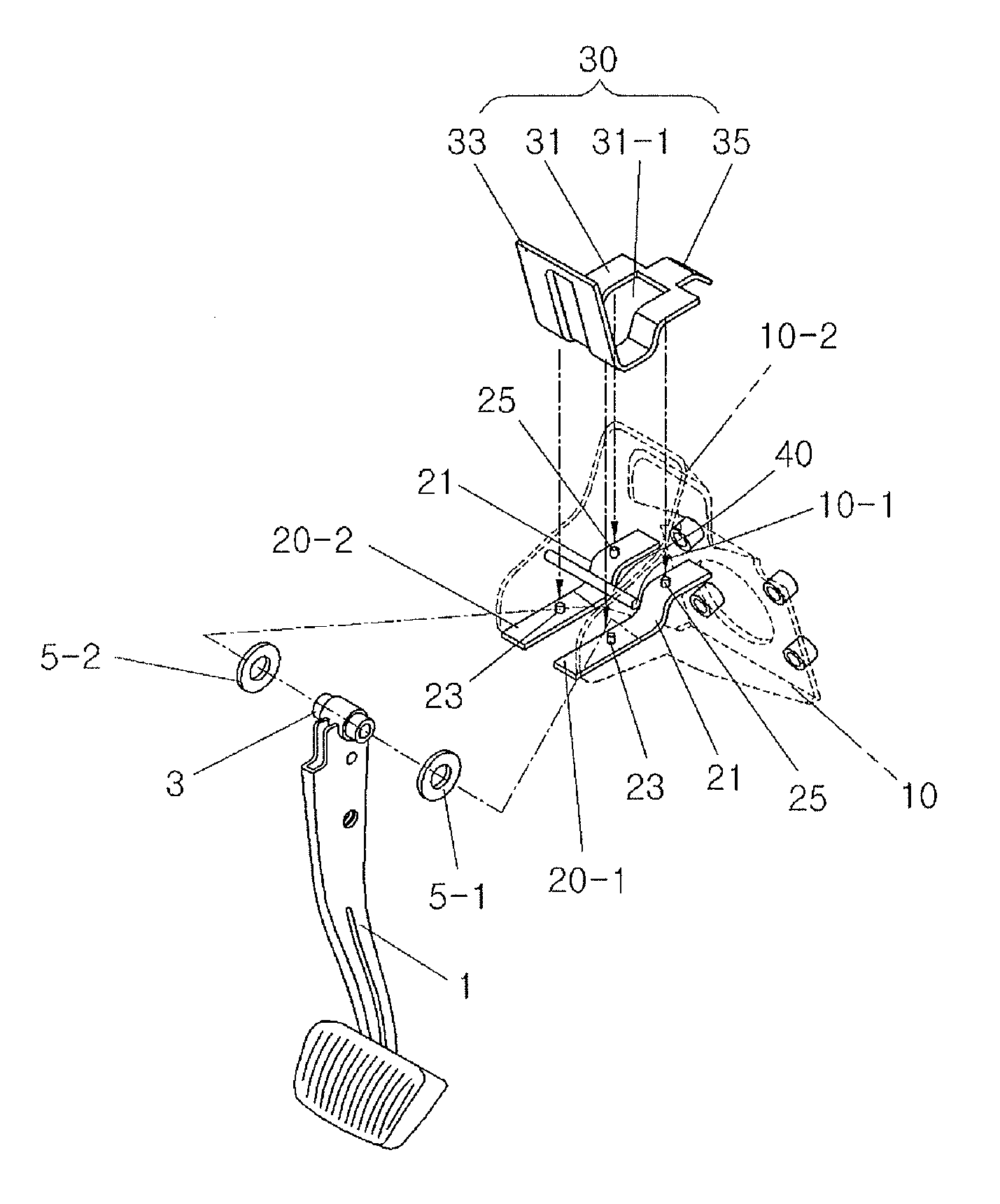
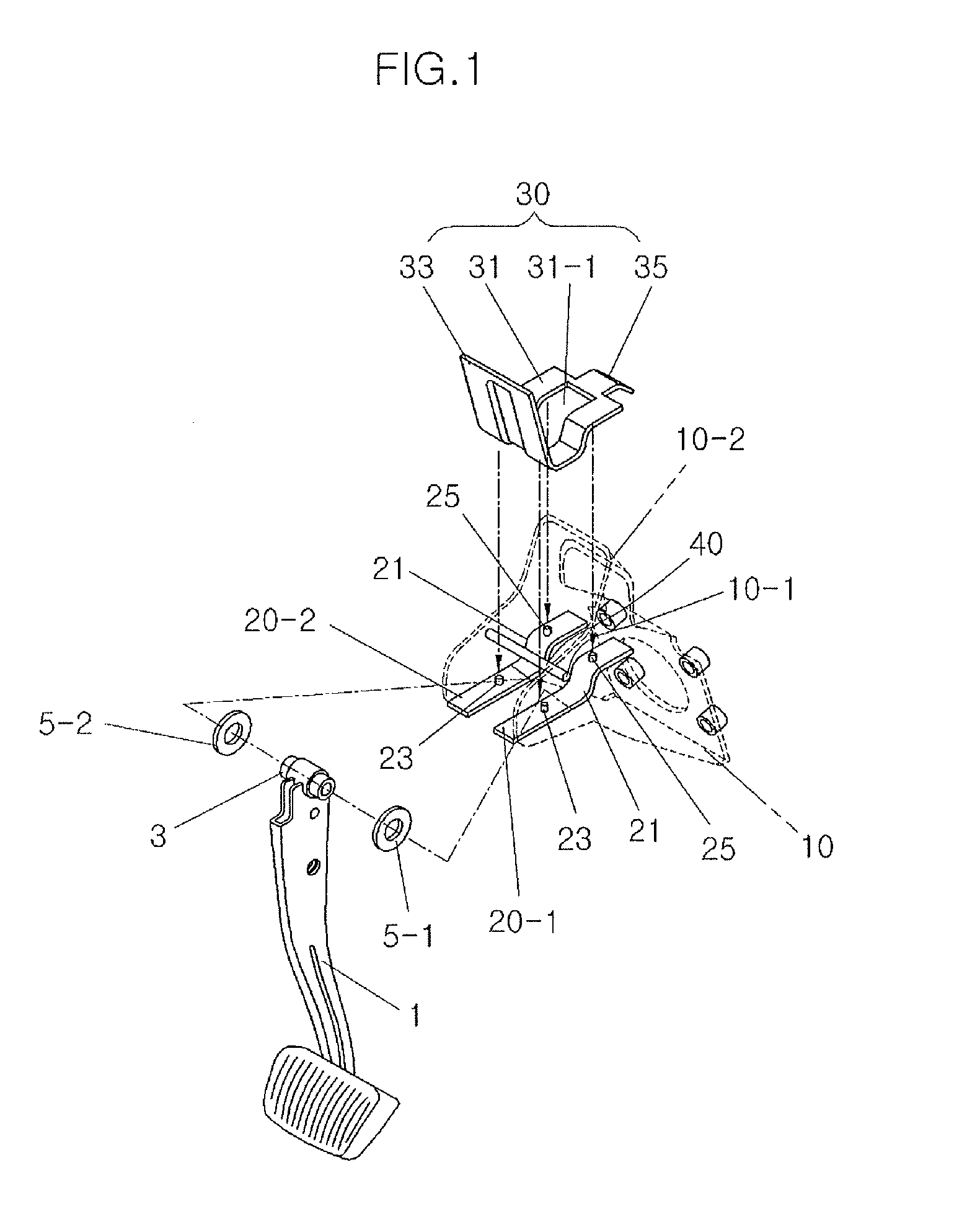
[0045]FIG. 1 is an exploded view illustrating a universal reverse configu...


PUM


Abstract

A driver's injury prevention type pedal may include a pedal arm which is rotatably coupled, at an upper portion to a pedal arm hinge which acts as a center of rotation of a pedal stroke, and a universal reverse rotation member which reversibly rotates the pedal arm about the pedal arm hinge and away from a driver which may include a mounting bracket to which the upper portion of the pedal arm is fitted and coupled, and a reverse rotation lever which presses the upper portion of the pedal arm by counterclockwise direction rotation formed by pushing of the pedal arm. In particular, the driver's injury prevention type pedal may be converted into a brake pedal, a clutch pedal, or an acceleration pedal, thereby allowing pedal manufacturing costs to be significantly reduced.

Description

CROSS-REFERENCE TO RELATED APPLICATION[0001]This application claims priority to Korean Patent Application No. 10-2013-0155820, filed Dec. 13, 2013, the entire contents of which is incorporated herein by this reference.BACKGROUND OF THE INVENTION[0002]1. Field of the Invention[0003]The present invention relates to a pedal; and more particularly, to a pedal in which all sorts of pedals may be converted into pedals for preventing driver's injury with no change of design by adopting a universal reverse rotation member for reversely rotating a pedal arm to prevent injury of a driver's leg part.[0004]2. Description of Related Art[0005]In the event of a forward collision of a vehicle, components such as a bumper and an engine are generally pushed rearward of an engine compartment due to an impact of the collision to thereby deform an interior structure separated from the engine compartment, resulting in injury to a driver mounted inside the vehicle by the collision.[0006]A driver typically...

Claims


Application Information

Patent Timeline
Patent Type & Authority Applications(United States)
IPC IPC(8): G05G1/30
CPCG05G1/30B60T7/065B60R21/09G05G1/327G05G1/44Y10T74/20528B60T7/06B60T7/04G05G1/32
Inventor KIM, EUN-SIK
Owner HYUNDAI MOTOR CO LTD
Why Eureka
Try Eureka