In-line vacuum lquid aspirator

a vacuum cleaner and liquid aspirator technology, applied in the field of vacuum cleaners, can solve the problems of limited one-time liquid collection capacity, heavy user handling and maneuverability, and easy damage to the electrical and electronic parts of the vacuum cleaner

Inactive Publication Date: 2015-06-25
KERR EDMUND JOHN
View PDF6 Cites 5 Cited by
  • Summary
  • Abstract
  • Description
  • Claims
  • Application Information

AI Technical Summary

Benefits of technology

[0008]According to a first embodiment of the present invention there is disclosed an apparatus for removing fluids from a vacuum flow path comprising a body defining a containment chamber having an inlet port connectable to a vacuum hose and a barrier wall within the containment chamber isolating a transfer chamber within the containment chamber. The containme

Problems solved by technology

However, the electrical and electronic parts of the vacuum cleaners are prone to getting damaged by the liquids.
This generally makes it heavy for the user to handle and maneuver during t

Method used


Image

  • In-line vacuum lquid aspirator
  • In-line vacuum lquid aspirator
  • In-line vacuum lquid aspirator

Examples


Embodiment Construction

[0019]The following description presents several preferred embodiments of the present invention in sufficient detail such that those skilled in the art can make and use the invention.

[0020]Before describing in detail embodiments that are in accordance with the present invention, it should be noted that all of the figures are drawn for ease of explanation of the basic teachings of the present invention only. The extension of the figures with respect to the number, position, relationship and dimension of the parts of the preferred embodiment will be within the skill of the art after the following teachings of the present invention have been read and understood. Further, the exact dimensions and dimensional proportions to conform to specific force, weight, strength and similar requirements will likewise be within the skill of the art after the following teachings of the present invention have been read and understood.

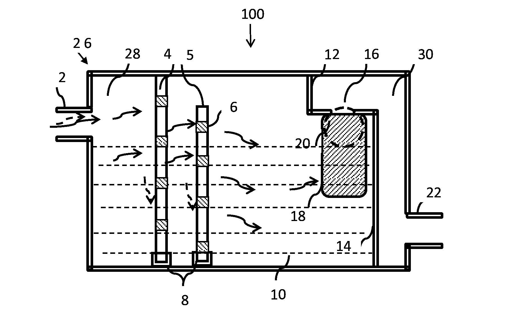
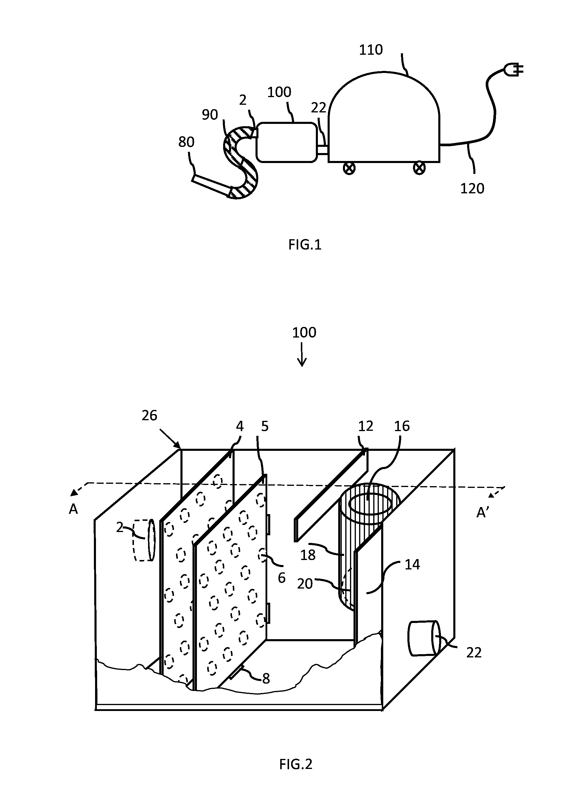
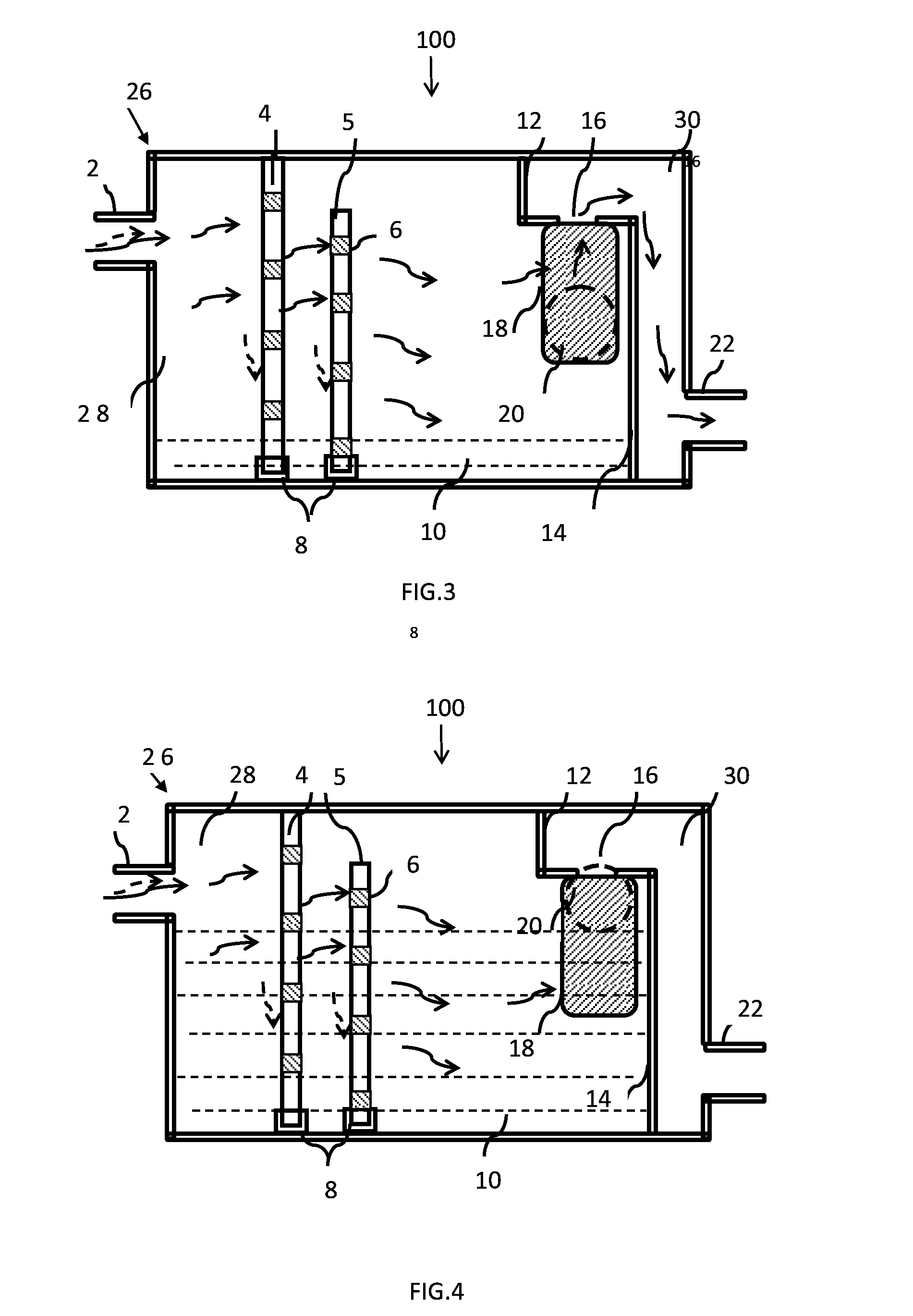
[0021]FIG. 1 is a representation of a possible configuration of the a...


PUM


Abstract

An apparatus for removing fluids from a vacuum flow path comprises a body defining a containment chamber having an inlet port connectable to a vacuum hose and a barrier wall within the containment chamber isolating a transfer chamber within the containment chamber. The containment chamber has an outlet port connectable to a vacuum hose. The transfer port has a suction port fluidicly connecting the transfer chamber and the containment chamber. The apparatus further comprises a float positioned below the transfer port and adapted to be raised into sealing contact with the transfer port as a fluid level in the containment chamber rises.

Description

BACKGROUND OF THE INVENTION[0001]1. Field of Invention[0002]The present invention relates to vacuum cleaners in general and in particular to a method and attachment for vacuuming liquids to as to prevent the liquids from entering the vacuum cleaner.[0003]2. Description of Related Art[0004]Vacuum cleaners are typically provided with a flexible hose that is connectable to a pick-up nozzle at one end and to a housing at the other end. The housing accommodates the filters for trapping the waste solid particles and an electric motor. An electrical cord for the electric motor protrudes out of the housing and is attachable to an external electric supply port. During operation, when the motor is switched on, air stream carrying the solid particles is sucked in through the nozzle and passed through the filter. The filter traps the solid particles substantially and the air stream is released back to the ambience.[0005]During the common processes of cleaning of floors and carpets by vacuum cle...

Claims


Application Information

Patent Timeline
IPC IPC(8): A47L7/00
CPCA47L7/0023A47L7/0028A47L7/0014Y10T137/0318Y10T137/7358Y10T137/742
Inventor KERR, EDMUND JOHN
Owner KERR EDMUND JOHN
Why Eureka
Try Eureka