Method for removing gases from a container having a powdered concentrate for use in hemodialysis

Active Publication Date: 2011-05-26
FRESENIUS MEDICAL CARE HLDG INC
View PDF0 Cites 62 Cited by
  • Summary
  • Abstract
  • Description
  • Claims
  • Application Information

AI Technical Summary

Benefits of technology

[0009]In an embodiment, a second valve is provided downstream the container to facilitate pressurization of the con

Problems solved by technology

The system cannot remove all of the air from the container without evacuating the air from the container via a vacuum system to create negative pressure, before filling the container with fluid.
In the systems kno

Method used


Image

  • Method for removing gases from a container having a powdered concentrate for use in hemodialysis
  • Method for removing gases from a container having a powdered concentrate for use in hemodialysis
  • Method for removing gases from a container having a powdered concentrate for use in hemodialysis

Examples


Embodiment Construction

[0015]For the purposes of this disclosure, the term “operating pressure” means the fluid or fluid pressure in the container having a powdered salt concentrate, during operation of the system, where the system is capable of supplying a concentrated salt solution to the dialysis apparatus. The term “flushing step” means operating the system to remove trapped gases from a container having a powdered salt concentrate, by pumping fluid through the container at a pressure that is greater than the operating pressure of the system, and directing the outflow out of the system to a drain, instead of to a dialysis apparatus.

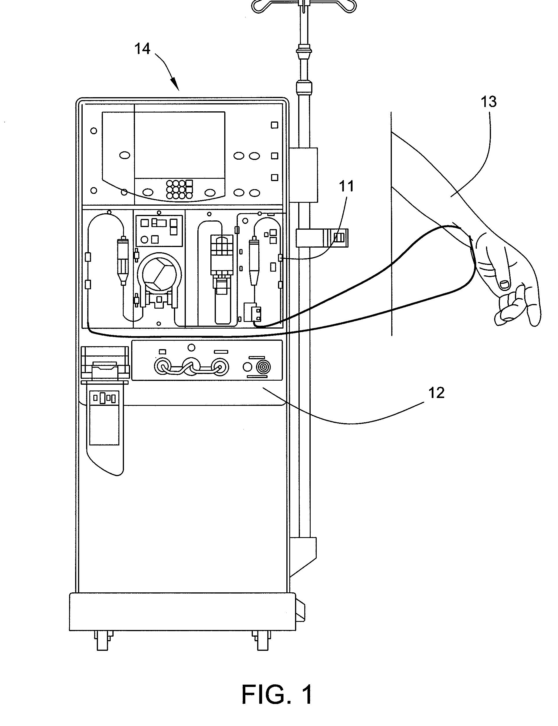
[0016]Turning now to the drawings, FIG. 1 displays the general context of a dialysis system 10. The dialysis system 10 includes the dialyzer 11, and a subsystem 12 for preparing a salt solution from a powdered salt concentrate for use in the dialyzer 11. The salt solution is provided to the dialyzer 11 for administration to a patient 13. The dialysis system 10 may additiona...


PUM

PropertyMeasurementUnit
Pressureaaaaaaaaaa
Levelaaaaaaaaaa

Abstract

An apparatus and a method for filling a container containing a dry powdered salt concentrate for use in dialysis with purified fluid and removing the trapped air or gases generated during the filling of the container, while maintaining the required fluid level in the container and without the need for evacuating gases from the container prior to filling.

Description

BACKGROUND OF THE INVENTION[0001]Dialysis is performed as a treatment for patients suffering from renal insufficiency. Dialysis can be performed either in the peritoneum, or through extracorporeal dialysis or filtration of blood. These two dialysis methods have in common the fact that dialysis fluids or dialysates take up the degradation products of metabolism. These dialysates usually contain high levels of sodium chloride and other electrolytes, such as calcium chloride, or potassium chloride, a buffer substance, such as bicarbonate, or acetate and acid to establish a physiological pH, plus optionally, glucose or another osmotic agent.[0002]Dialysates are either supplied as ready-to-use solutions or they are prepared on site from concentrates, including solid concentrates. Solids offer the advantage of a small package volume and a low weight. Although solids also have disadvantages—electrolyte salts, for example, are highly hygroscopic—there is a trend toward offering only solid c...

Claims


Application Information

Patent Timeline
IPC IPC(8): B01D61/26B01D61/32
CPCA61M1/1658A61M1/167A61M1/1666
Inventor LEVIN, ROLANDRAIFORD, WAYNE
Owner FRESENIUS MEDICAL CARE HLDG INC
Why Eureka
Try Eureka