Pressurized pen

a pressurized pen and pen body technology, applied in the field of pen, can solve the problems of insufficient sealing ability, insufficient outer diameter precision of the loop, and insufficient use of the pen in the course of writing down notes, etc., and achieve the effects of small force, easy knocking operation, and excellent use feeling

Active Publication Date: 2009-10-20
TOMBOW PENCIL CO LTD
View PDF12 Cites 5 Cited by
  • Summary
  • Abstract
  • Description
  • Claims
  • Application Information

AI Technical Summary

Benefits of technology

[0010]The invention has been made in consideration of the above-mentioned disadvantages involved with prior pens. Accordingly it is an object of the invention to provide an improved pressurized pen. Another object of the invention is to provide a pressurized pen having excellent feeling of using it by allowing an easy knocking operation with small force.
[0015]A compressive deformation is caused by a pressurizing member of a press pump mechanism configured so as to freely expand and contract in an axial direction, and a pressing member configured so as to interlock with a pressing operation of the knock mechanism. Therefore, since the system configured to pressurize an inside of the medium containing tube is possible to easily compress and deform the pressurizing member, it is possible to obtain a pressurized pen having excellent feeling of using the pen by allowing an easy knocking operation with small force.
[0016]The pressurizing member includes an elastic cylindrical member, and the elastic cylindrical member includes a large-diameter front cylinder portion of which a front end air-tightly communicates directly with the rear opening portion of the medium containing tube and which forms the pressurizing chamber, and a small-diameter rear cylinder portion which is coaxially connected to a rear end of the front cylinder portion and in which the front end portion of the pressing member is pressed into a rear aperture thereof. By allowing the pressing member to press the rear cylinder portion into the front cylinder portion, the pressurizing chamber is formed to be an airtight state, and thus it is possible to easily compress and deform the pressurizing member.
[0017]According to the embodiment of invention, the pressing member follows a rotor in the knock mechanism, and the elastic cylindrical member is compressed to pressurize the inside of the medium containing tube, and the pen tip is made to protrude from the front end portion of the barrel by the pressing operation of the knock bar. Therefore, it is possible to easily pressurize in the medium containing tube.
[0018]According to other embodiment of the invention the inside of the medium containing tube can maintain a pressurized state when using the pen, therefore it is effective in preventing the rack of ink particularly when the pen tip is used in an upward state.

Problems solved by technology

Conventional pens such as ball-point pens have the disadvantage in that a pen tip must be rubbed several times on a paper whenever the ink doesn't smoothly come out of a pen tip of a pen refill unit at the time of using the pen, or the ink is exhausted in the course of writing down on notes.
However, when fabricating the loop-shaped elastic ring, outer diameter precision of the loop-shaped elastic ring may be lowered by irregularities of the outer diameter or burrs caused by joint lines of a mold, and thus the case where the sealing ability is not sufficient occasionally occurs.
Then, conversely, there is a problem of deteriorating the feeling of using the pen since the large force is needed to perform the knocking operation at the time of using the pen.

Method used


Image

  • Pressurized pen
  • Pressurized pen
  • Pressurized pen

Examples


Embodiment Construction

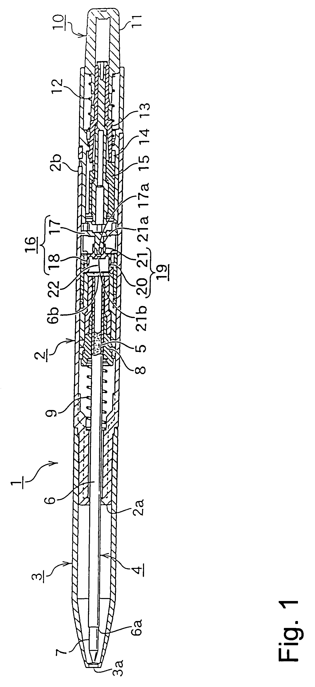
[0028]Hereinafter, the invention will be described in detail with reference to embodiments thereof showing a knock-type ball-point pen as an example and the drawings.

[0029]In FIG. 1, “left side” is defined as “the front”, and “right side” is defined as “the rear” of the pen.

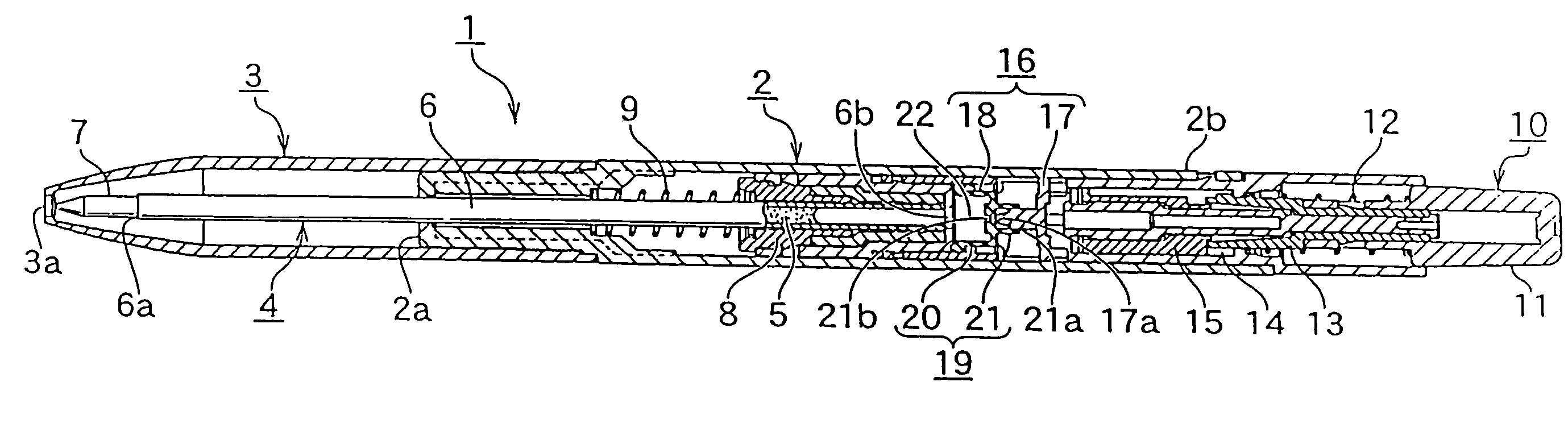
[0030]As shown in the FIG. 1, in a ball-point pen 1 of the invention, the pen holder is formed of a barrel 2 and a front member 3 screwed onto a front end section 2a of the barrel 2, and a pen refill unit 4 is loaded in the pen holder.

[0031]The pen refill unit 4 includes an ink containing tube 6 filled with ink 5 as a medium for writing, a pen tip 7 loaded on a front end portion 6a of the ink containing tube 6. The pen tip 7 is configured to protrude and retreat from the front aperture section 3a of the front member 3 to the outside by operating the pen refill unit 4 which will be mentioned later.

[0032]A rear opening portion 6b of the ink containing tube 6 is kept and held by a holder 8 which is a member sliding ...


PUM


Abstract

A pressurized pen having excellent feeling of using it by allowing an easy knocking operation with small force is disclosed. The pressurizing member 18 includes an elastic cylindrical member 19. The elastic cylindrical member 19 has a large-diameter front cylinder portion of which a front end 20a in air-tight manner communicates directly with the rear opening portion 6b of an ink containing tube 6 and which forms the pressurizing chamber 22, and a small-diameter rear cylinder portion 21 which is coaxially connected to a rear end of the front cylinder portion 20 and in which the front end portion 17a of the pressing member 17 is pressed into a rear aperture 21a thereof. The inside of the ink containing tube 6 is pressurized by allowing the pressing member 17 to press the rear cylinder portion 21 into the front cylinder portion 20 and compressing the elastic cylindrical member 19 in the axial direction with the pressing chamber 22 air-tight.

Description

BACKGROUND OF THE INVENTION[0001]1. Field of the Invention[0002]The present invention relates to a pen such as a ball-point pen, a correction pen, or a glue pen, and more particularly to a pressurized pen enabling smooth supply of medium such as ink, correction fluid, or glue at the time of using the pen.[0003]2. Description of the Related Art[0004]Conventional pens such as ball-point pens have the disadvantage in that a pen tip must be rubbed several times on a paper whenever the ink doesn't smoothly come out of a pen tip of a pen refill unit at the time of using the pen, or the ink is exhausted in the course of writing down on notes.[0005]In this regard, as disclosed in the JP 2005-280119 A, a knock-type ball-point pen is known, in which a press pump mechanism formed of a cylinder and a piston is disposed in a pen refill unit of the pen, a loop-shaped elastic ring made for example of rubber is disposed on a front end portion of the piston that is in sliding contact with an inner p...

Claims


Application Information

Patent Timeline
Patent Type & Authority Patents(United States)
IPC IPC(8): B43K5/18B43K5/02
CPCB43K7/03B43K24/08B43M11/06B43L19/0068B43L19/0018B43K24/00
Inventor TANIGUCHI, SHUNICHI
Owner TOMBOW PENCIL CO LTD
Why Eureka
Try Eureka