Motor rotation axis, thrust bearing structure of motor rotation axis

A motor, rotating shaft technology, applied in the direction of rotating bearings, shafts and bearings, sliding contact bearings, etc., can solve problems such as abnormal sound or vibration, increased rotational resistance, and loose motor rotation, and achieves suppression of abnormal sound or vibration. , the effect of reducing the rotation resistance and reducing the manufacturing cost

Inactive Publication Date: 2005-04-20
DENSO CORP
View PDF0 Cites 6 Cited by
  • Summary
  • Abstract
  • Description
  • Claims
  • Application Information

AI Technical Summary

Problems solved by technology

[0004] However, it is well known that the surface of the machined part to be machined becomes rough due to the remaining cutting marks of the cutting tool, and even if finishing cutting is performed, the cutting marks remain on the cutting surface, so it is difficult to obtain high-precision roughness on the tip surface. degree (very small roughness)
In addition, since chips are generated by cutting, the chips adhere to the motor shaft and may enter between the head end surface of the motor shaft and the resin member during motor assembly.
[0005] When the roughness of the head end surface of the motor rotating shaft is large, or when chips enter between the head end surface and the thrust bearing, the rotation resistance of the motor will increase when the motor rotates, resulting in abnormal sound or vibration, and at the same time, The problem of loosening when the motor rotates due to partial wear of the resin member
In addition, in order to prevent problems caused by swarf, it is necessary to perform, for example, a cleaning process to remove swarf, resulting in an increase in manufacturing costs.

Method used


Image

  • Motor rotation axis, thrust bearing structure of motor rotation axis
  • Motor rotation axis, thrust bearing structure of motor rotation axis
  • Motor rotation axis, thrust bearing structure of motor rotation axis

Examples


Embodiment Construction

[0042] Hereinafter, an embodiment embodying the present invention will be described with reference to the drawings.

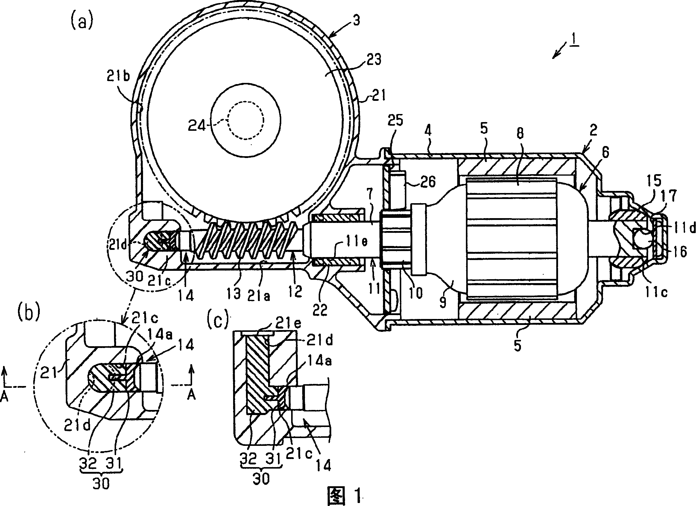
[0043] FIG. 1(a) shows the motor 1 of this embodiment. The electric motor 1 of the present embodiment is an electric motor used as a drive source of a vehicle wiper device, and is an electric motor with a reduction mechanism in which a motor main body 2 and a reduction unit 3 housing the reduction mechanism are integrally assembled.

[0044] The motor main body 2 is composed of a DC motor and has a bottomed cylindrical yoke housing 4 . A pair of magnets 5 are fixed to the inner surface of the yoke case 4 , and an armature 6 is rotatably housed inside the magnets 5 . The armature 6 has an armature shaft 7 , a core 8 , winding wires 9 and a commutator 10 .

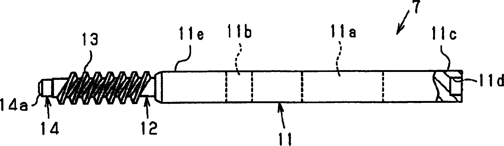
[0045] The armature shaft 7, which is the rotating shaft of the motor, is made of metal, such as figure 2 As shown, a predetermined part from the base end to the head end is the shaft body 11, and the side...


PUM


Abstract

The present invention provides a high-precision motor rotating shaft. The armature shaft (7) has a thrust force at one end that is in contact with a resin member (30) provided on a gear case (21) of the motor (1) to bear its thrust load. Receiving surface (14a). The thrust receiving surface (14a) is composed of a roll finish surface obtained by rolling a cut surface formed into a predetermined shape by rough cutting. In addition, the armature shaft 7 has a worm (13) that engages with a worm wheel (23).

Description

technical field [0001] The present invention relates to a motor rotating shaft, a thrust bearing structure of the motor rotating shaft, a motor with a reducer, and a method for manufacturing the motor rotating shaft. Background technique [0002] Conventionally, as a thrust bearing structure of a motor rotating shaft of a motor, a structure in which a resin member is provided at the shaft end of a motor rotating shaft rotatably supported by a motor housing and the thrust of the motor rotating shaft is received by the resin member is known. (For example, refer to Patent Document 1). The resin member is formed by injecting molten resin into the hollow portion of the motor housing with the head end portion of the motor rotating shaft inserted into the hollow portion and hardening it. When the resin member is cured, since it shrinks along the tip, a slight gap is formed between the tip and the same tip, so that the motor can be rotated while being correctly positioned in the th...

Claims


Application Information

Patent Timeline
Patent Type & Authority Applications(China)
IPC IPC(8): F16C17/08F16C33/06F16H1/16H02K5/14H02K5/167H02K7/06H02K15/14
CPCF16H1/16
Inventor 斋藤聪
Owner DENSO CORP
Why Eureka
Try Eureka