Power tool dust collecting device and power tool

a technology of dust collection device and power tool, which is applied in the direction of woodworking apparatus, turning machine accessories, percussive tools, etc., can solve the problems of affecting the efficiency of removing dust from the filter, blowing away dust generated, etc., and achieves efficient pressurization, simple operation of compressing the pump, and convenient pressurization

Active Publication Date: 2014-11-04
MAKITA CORP
View PDF15 Cites 5 Cited by
  • Summary
  • Abstract
  • Description
  • Claims
  • Application Information

AI Technical Summary

Benefits of technology

[0005]In light of the above, the present invention provides a power tool dust collecting device having improved efficiency when dust from a filter is removed, and a power tool on which the power tool dust collecting device is mounted.
[0013]According to the power tool dust collecting device of the first aspect of the invention and the power tool according to the eleventh aspect of the invention, air pumped by the air pumping unit flows in reverse from the downstream side to the upstream side of the filter and can thus blow away dust attached to the filter. As a result, efficiency of separating dust from the filter improves.
[0014]According to the second aspect of the invention, the air pumped by the air pumping unit to flow in reverse from the downstream side to the upstream side of the filter. As a result, dust that has attached to the filter can be effectively blown away.
[0016]According to the fourth aspect of the invention, the fan chamber can be easily pressurized by simple operation of compressing the pump.
[0017]According to the fifth aspect of the invention, by closing the discharge opening of the fan chamber with the shutter member, air pumped into the fan chamber is prevented from leaking out through the discharge opening.
[0018]According to the sixth aspect of the invention, when the air is pumped into the fan chamber by the compression operation of the pump using the operation unit, the discharge opening formed in the fan chamber can be closed by using the shutter member. As a result, inside of the fan chamber can be efficiently pressurized using the air pumped from the pump.

Problems solved by technology

According to the disclosed power tool, an airflow passing through the inflow opening flows along the filter surface inside the suction mechanism, and thus blows away dust generated by cutting that is attached to the filter surface.
However, in the above-described power tool, even if the dust attached to the filter surface can be temporarily blown away by the airflow passing through the inflow opening, dust etc. in the airflow may attach to the filter surface again.
Thus, efficiency for removing the dust from the filter may deteriorate.

Method used


Image

  • Power tool dust collecting device and power tool
  • Power tool dust collecting device and power tool
  • Power tool dust collecting device and power tool

Examples


first embodiment

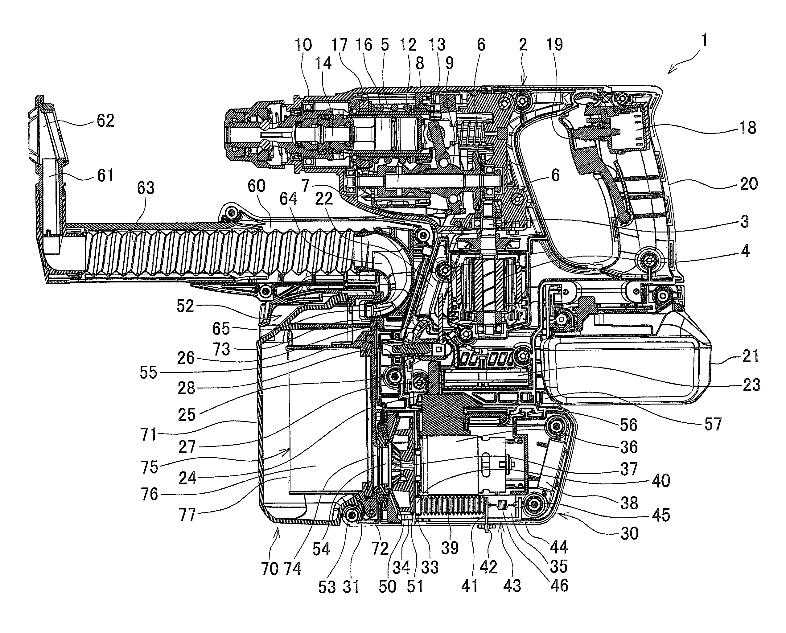
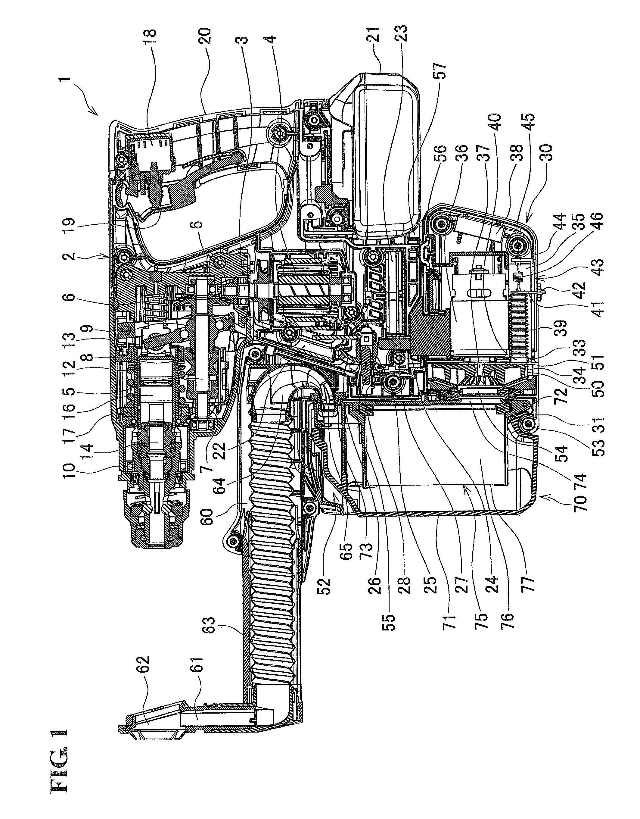
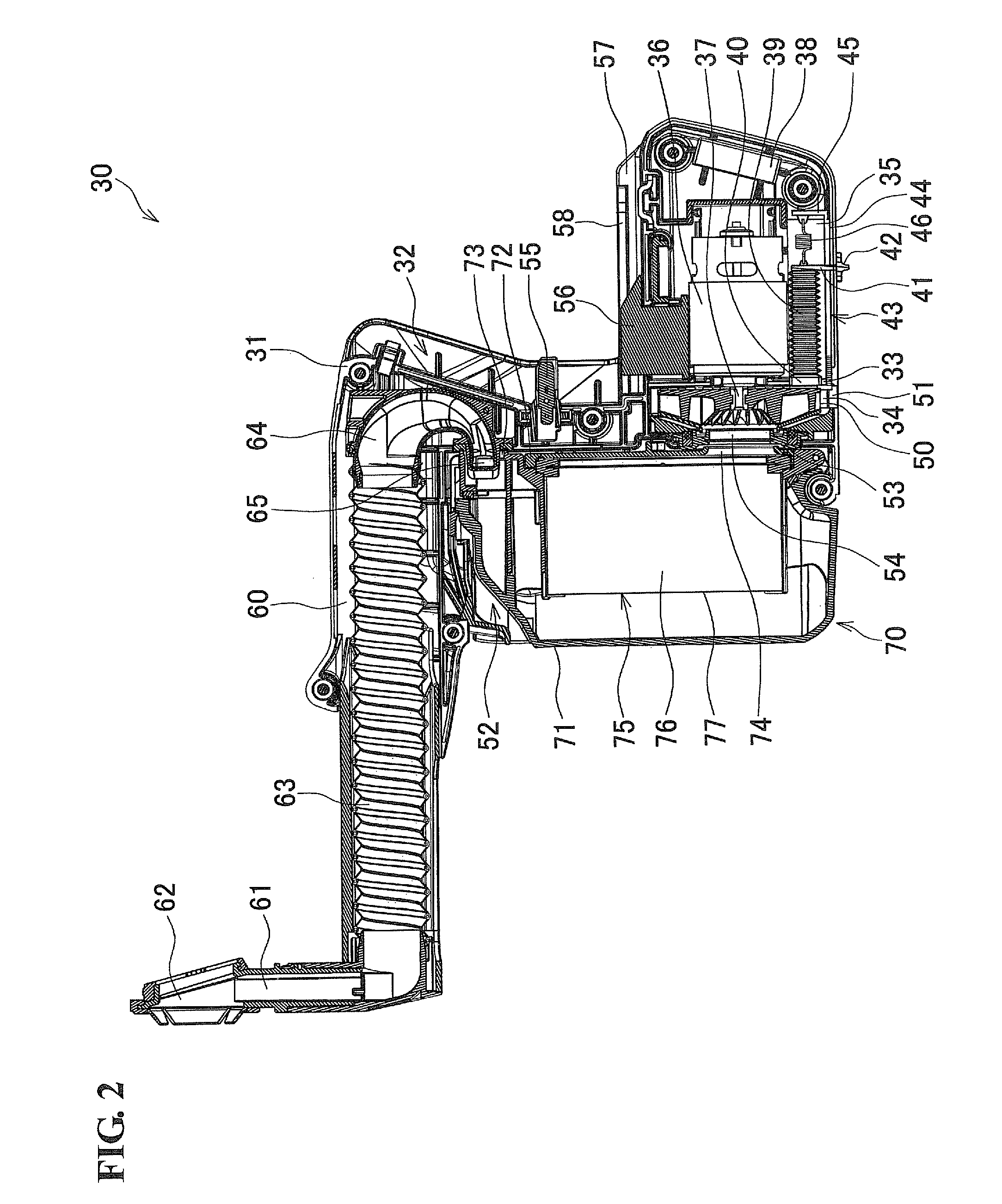
[0028]the present invention will be explained with reference to FIG. 1 to FIG. 3. FIG. 1 shows a state in which a power tool dust collecting device 30 is mounted on a hammer drill 1, and FIG. 2 shows the power tool dust collecting device 30 (hereinafter referred to as the dust collecting device 30). The hammer drill 1 is an example of a power tool of the present invention, and is provided with a main housing 2 made of resin. The left side in FIG. 1 is the front side of the main housing 2 and the right side in FIG. 1 is the rear side of the main housing 2. As shown in FIG. 1, a motor 4 having an upwardly facing output shaft 3 is housed in the lower portion on the front side inside the main housing 2. Above the output shaft 3 inside the main housing 2, a countershaft 5 is axially supported in a direction intersecting with the output shaft 3, and torque is transmitted from the output shaft 3 to the countershaft 5 via bevel gears 6. The countershaft 5 has a first gear 7, a clutch 8 and ...

second embodiment

[0055]Hereinafter, the present invention will be explained based on the drawings.

[0056]FIG. 4 shows a cross-section in which a power tool dust collecting device (hereinafter simply referred to as a “dust collecting device”) is mounted on a hammer drill that is an example of a power tool.

[0057]First, a hammer drill 101 includes a motor 103 that is accommodated in the lower portion of the front side (the front is the left side in FIG. 4) of a housing 102 formed by assembling a left and right pair of half housings. An output shaft 104 of the motor 103 faces in the upward direction. Torque is transmitted from the output shaft 104 to a countershaft 106, via bevel gears 105, 105 that are positioned above the output shaft 104. The countershaft 106 is provided with the first gear 7, the clutch 8 and the boss sleeve 9 in that order from the front side. Above the countershaft 106, a tool holder 111 is axially supported in parallel with the countershaft 106 and a bit 110 can be inserted into a...


PUM

PropertyMeasurementUnit
pressureaaaaaaaaaa
torqueaaaaaaaaaa
shapeaaaaaaaaaa

Abstract

A power tool dust collecting device includes a fan chamber and a dust collecting chamber. The fan chamber is formed in a housing which is mountable on a hammer drill and in which a suction opening is provided protrudingly. The fan chamber houses a fan that rotates in accordance with driving of a motor. The dust collecting chamber is formed on an upstream side of the fan chamber. Mounted on the dust collecting chamber is a filter through which passes air that has been sucked up from the suction opening by the rotation of the fan and which collects dust included in the air. An air pumping unit that pumps air from a downstream side of the filter toward an upstream side is provided inside the housing.

Description

BACKGROUND OF THE INVENTION[0001]This application claims the benefit of Japanese Patent Application Number 2011-171091 filed on Aug. 4, 2011 and Japanese Patent Application No. 2011-189337 filed on Aug. 31, 2011, the entirety of which is incorporated by reference.TECHNICAL FIELD[0002]The present invention relates to a power tool dust collecting device that is mounted on a power tool, such as a power drill or a hammer drill etc., and to a power tool on which the power tool dust collecting device is mounted.RELATED ART[0003]In Japanese Patent No. 3448110, for example, a power tool is disclosed that is provided with a dust collecting device for collecting dust generated when concrete etc is cut. In the power tool disclosed in Japanese Patent No. 3448110, a suction mechanism having a filter collecting dust generated by cutting is detachably mounted on a main body of a device, and an inflow opening is provided in the suction mechanism, the inflow opening extending substantially at a righ...

Claims


Application Information

Patent Timeline
Patent Type & Authority Patents(United States)
IPC IPC(8): B23B47/34B01D50/00B23Q11/00
CPCB23Q11/0046Y10T408/50Y10T408/453Y02P70/10
Inventor MACHIDA, YOSHITAKAYOSHIKANE, KIYONOBU
Owner MAKITA CORP
Why Eureka
Try Eureka